Emitter Parameters in the Inspector
These parameters (in the Emitter Controls group) determine how particles are distributed
and rendered in your project. The Emitter Inspector has a large number of parameters,
some of which depend on the settings of other parameters in the Inspector. All
combinations of parameters are described below.
Shape:
The first parameter in the Emitter Inspector is the Shape pop-up menu. When 3D
is turned off, nine options are available. When the 3D checkbox is selected, two additional
shapes become available. Different shapes significantly alter the distribution of generated
particles. When you choose an emitter shape, different Emitter Inspector parameters
appear that are unique to that shape. For example, when Rectangle is the selected shape,
Outline, Tile Fill, and Random Fill become available in the Arrangement options. When
Spiral is the selected shape, the Arrangement parameter goes away and new parameters
such as Radius, Number of Arms, and Twists become available. These different parameters
provide additional control over the distribution of particles.
In addition, when the 3D checkbox is selected, the Render Particles, Emission Latitude,
Emission Longitude, and Depth Ordered parameters become available for all emitter
shapes.
• Point: This is the simplest emitter shape and is the default shape for new emitters. It
specifies a single point of emission for a particle system. There are no additional
parameters for the Point shape.
693
Chapter 14
Working with Particles
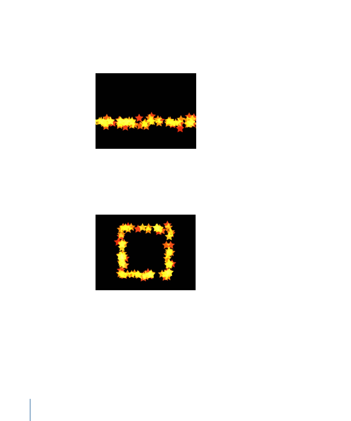
• Line: Particles emerge from a line. Using the onscreen controls (with the Adjust Item
tool) or the Properties Inspector, you can specify the length and location of the line. In
the Inspector, you can set a specific number of points where particles emerge. This
emitter shape is good for creating sheets of particles that cascade over a wide area.
The Line shape displays additional parameters.
• Rectangle: Particles emerge from a rectangle along its edge, or in a tile-fill or random-fill
pattern. Using the onscreen controls (with the Adjust Item tool), you can specify the
size and location of the rectangle. Drag the corners to adjust width and height; drag
edges to adjust width or height independently. Depending on the selected Arrangement,
the Rectangle emitter shape displays additional parameters. In the following image,
the Emitter shape Arrangement parameter is set to Outline.
Use the following modifier keys to more precisely manipulate the corners of the
Rectangle onscreen controls (with the Adjust Item tool):
• Option: Adjustments to size are scaled uniformly, with the anchor point remaining
fixed.
• Shift: Adjustments to size are made proportionally.
694
Chapter 14
Working with Particles
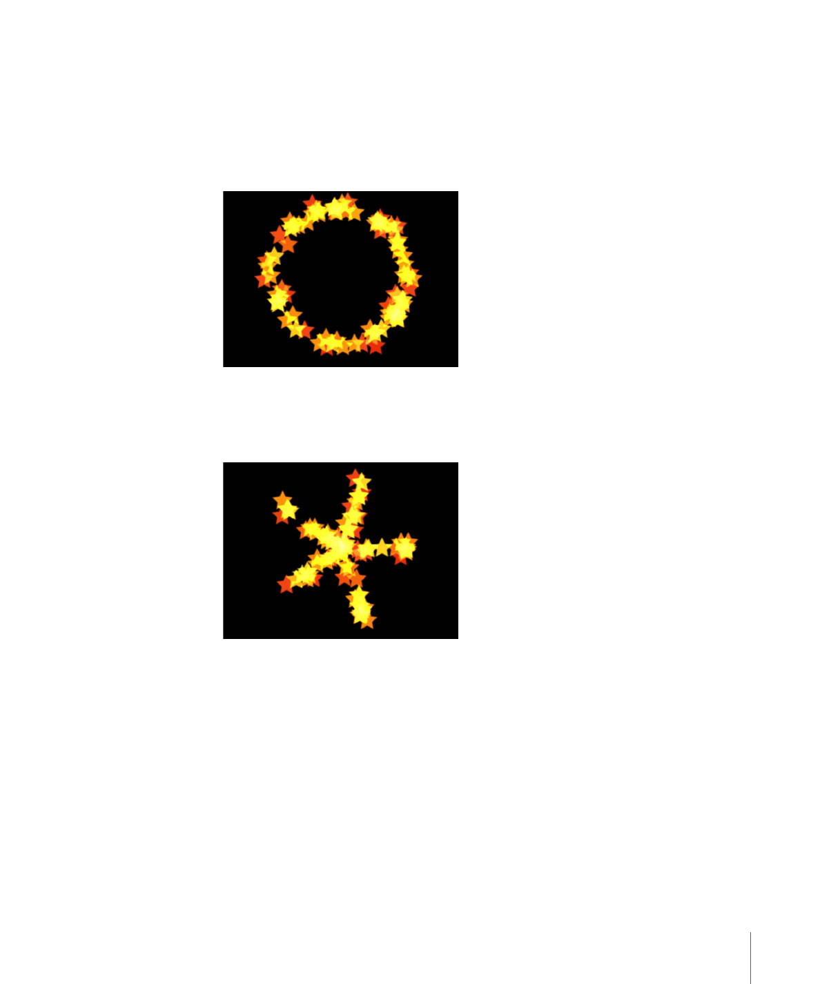
• Circle: Particles emerge from a circle-shaped emitter. Particles can be emitted in an
outline, tile-fill, or random-fill pattern. This emitter shape is good for surrounding an
element in a composition with particles that emerge from its edge. Using the onscreen
controls (with the Adjust Item tool), you can specify the size and location of the circle.
Depending on the selected Arrangement, the Circle emitter shape displays additional
parameters. In the following image, the shape’s Arrangement parameter is set to Outline.
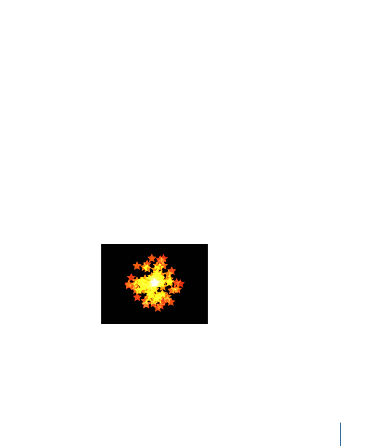
• Burst: Particles emerge from a burst pattern. Using the onscreen controls (with the
Adjust Item tool), you can specify the size and location of the burst. The Burst shape
displays additional parameters.
695
Chapter 14
Working with Particles
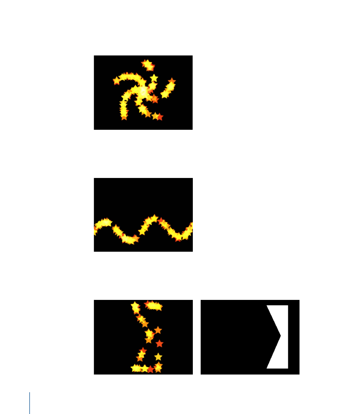
• Spiral: Particles emerge from a spiral pattern. Using the onscreen controls (with the
Adjust Item tool), you can specify the size and location of the spiral. The Spiral shape
displays additional parameters.
• Wave: Particles emerge from a waveform. Using the onscreen controls (with the Adjust
Item tool) or the Start Point and End Point parameters in the Emitter Inspector, you
can specify the length and location of the wave. The Wave shape displays additional
parameters.
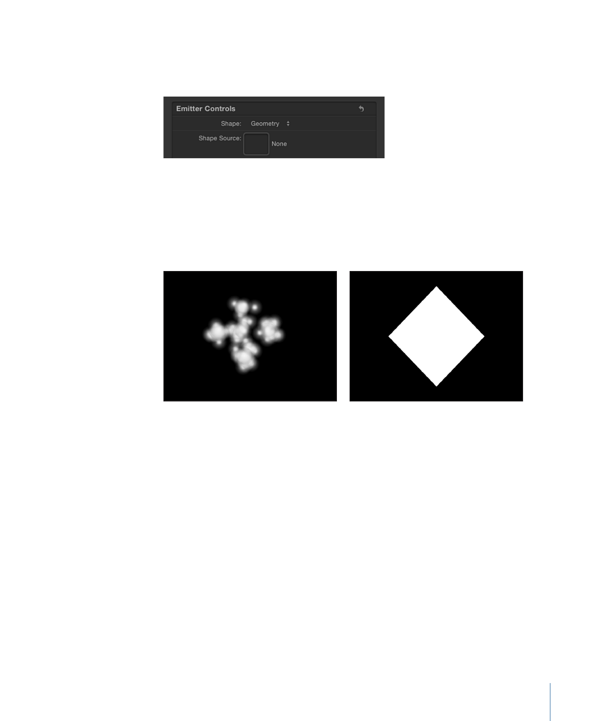
• Geometry: Particles emerge from the edge of a shape, defined by a spline object used
as the shape source. The Geometry shape displays additional parameters. The following
image on the right shows the shape used as the emitter source. The image on the left
shows particles emerging from the edge of the shape source.
696
Chapter 14
Working with Particles
To apply a shape as the geometry shape source for a particle emitter, drag the shape
to the Shape Source well in the Emitter Inspector (after Geometry is chosen from the
Shape pop-up menu).
• Image: Particles emerge from within an area defined by an image or from only the
edges of the image. The image may or may not have an alpha channel. If it does, the
shape of the alpha channel can also be used to define the emitter shape. The Image
shape displays additional parameters. The following image on the right shows the
image used as the emitter image source. The image on the left shows the particles
emerging from within the image.
To apply an image as the image source for a particle emitter, drag the image to the
Image Source well in the Emitter Inspector (after Image is chosen from the Shape
pop-up menu).
697
Chapter 14
Working with Particles
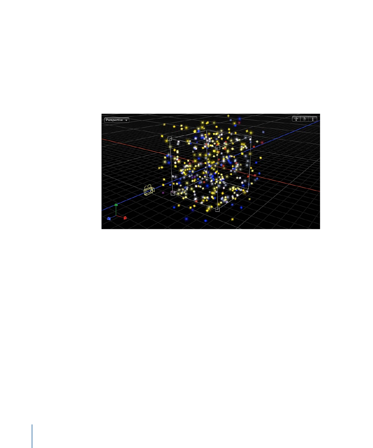
• Box: This option is available when the 3D checkbox is selected in the Emitter Inspector.
Particles are emitted from a three-dimensional cube along its surface (Outline), or in a
tile-fill or random-fill pattern. Using the onscreen controls (with the Adjust Item tool),
you can specify the size and location of the rectangle. Drag the front horizontal edge
to adjust height; drag the front vertical edge to adjust width; drag a back edge to adjust
depth; drag a front corner to simultaneously adjust the width and height. To reposition
the emitter, drag in the shape (but not on an edge or corner point). Depending on the
selected Arrangement, the Box shape displays additional parameters. In the following
image, the box’s Arrangement is set to Tile Fill.
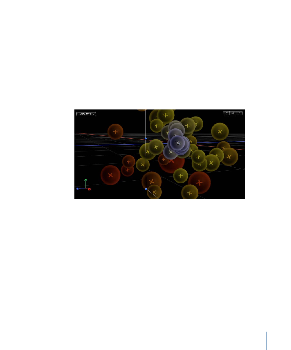
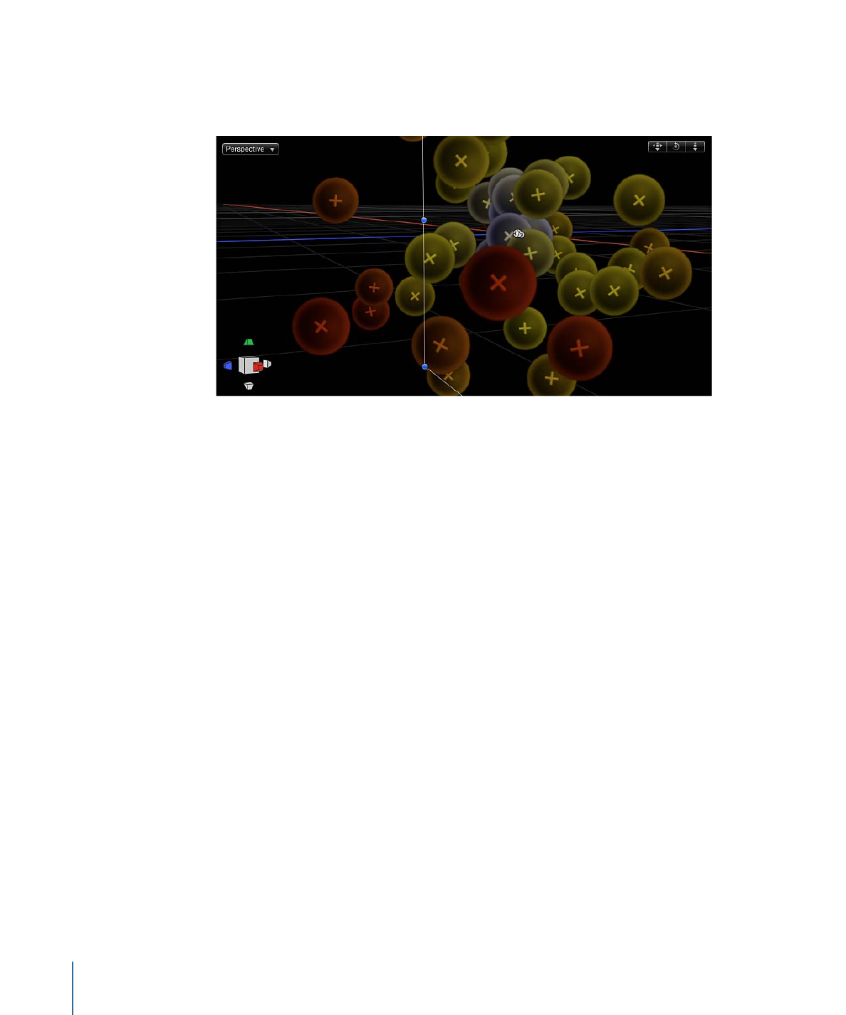
• Sphere: This option is available when the 3D checkbox is selected in the Emitter
Inspector. Particles are emitted from a three-dimensional sphere along its surface
(Outline), or in a tile-fill or random-fill pattern. Using the onscreen controls (with the
Adjust Item tool), you can specify the radius and location of the sphere. Drag the outline
of the sphere to adjust its radius; drag in the sphere to reposition it in the Canvas. When
Sphere is selected, the Arrangement parameter becomes available. Depending on the
selected Arrangement, the Sphere shape displays additional parameters.
Arrangement:
This pop-up menu, available when Rectangle, Circle, Image, Box, or Sphere
is chosen in the Shape pop-up menu, specifies the pattern from which the particles are
generated. The arrangement options are:
• Outline: Emits particles along the edge of the shape in 2D emitters and along the surface
of the shape in 3D emitters.
• Tile Fill: Emits particles from a tiled pattern of rows, columns, and ranks (for 3D emitters)
in the circle, rectangle, image, box, or sphere. You can specify the number of columns,
rows, and ranks, as well as the Tile Offset.
• Random Fill: Emits particles randomly from within the circle, rectangle, image, box, or
sphere.
698
Chapter 14
Working with Particles

Size:
This slider becomes available when Rectangle or Box is chosen in the Shape pop-up
menu. Defines the size of the rectangle or cube from which particles are emitted. The
Size slider is available whether the Arrangement is set to Outline, Tile Fill, or Random Fill.
When Rectangle is the selected shape, the Width and Height parameters become available.
When Box is selected, an additional Depth parameter is available.
Note: The Height is measured in project pixels; however, the Width is measured in square
pixels. This is done so a shape that is numerically square will look square when Correct
for Aspect Ratio is turned on (checkmarked) in the View pop-up menu in the top-right
corner of the Canvas.
Columns:
This slider becomes available when one of the following is chosen in the Shape
pop-up menu: Rectangle, Circle, Image, Box, or Sphere; in addition, Arrangement must
be set to Tile Fill. This parameter specifies the number of horizontal emitter points on a
grid over the selected emitter shape. In the case of an irregular shape (nonrectangular),
grid points that fall outside of the shape are ignored.
Rows:
This slider becomes available when one of the following is chosen in the Shape
pop-up menu: Rectangle, Circle, Image, Box, or Sphere; in addition, Arrangement must
be set to Tile Fill. This parameter specifies the number of vertical emitter points on a grid
over the selected emitter shape. In the case of an irregular shape (nonrectangular), grid
points that fall outside of the shape are ignored.
Ranks:
This slider becomes available when Box or Sphere is chosen in the Shape pop-up
menu and Tile Fill is the selected Arrangement. This parameter specifies the number of
points in Z space on a grid over the selected shape from which particles are emitted.
Tile Offset:
This slider becomes available when one of the following is chosen in the
Shape pop-up menu: Rectangle, Circle, Image, Box, or Sphere; in addition, Arrangement
must be set to Tile Fill. Values from 0 to 100% offset the rows toward the right, and values
from 0 to –100% offset the rows toward the left. A value of 50 or –50% creates a
“brickwork” pattern.
Image Source:
This image well, available when Image is chosen in the Shape pop-up
menu, lets you specify the object used to define the shape of the emitter.
Shape Source:
This image well, available when Shape is set to Geometry, lets you specify
a spline object to define the shape of the emitter.
Emission Alpha Cutoff:
This slider becomes available when Image is chosen in the Shape
pop-up menu. When the Image Source object contains an alpha channel, this slider
defines the minimum opacity value necessary to create particles at that point on the
source image. For example, when set to 25%, particles appear only where the alpha value
of the image is equal to or greater than 25% opacity. The lower the Emission Alpha Cutoff
value, the more particles appear. For this parameter to be effective, the alpha channel
must have areas of varying transparency.
699
Chapter 14
Working with Particles

Start Point:
This parameter, which becomes available when Shape is set to Line or Wave,
consists of two value sliders that define, in X and Y coordinates, the first point of the line
used as the emitter shape. Click the disclosure triangle to modify the Z position of the
start point. You can adjust these values in the Canvas using the onscreen controls (with
the Adjust Item tool).
End Point:
This parameter, which becomes available when Shape is set to Line or Wave,
consists of two value sliders that define, in X and Y coordinates, the second point of the
line used as the emitter shape. Click the disclosure triangle to modify the Z position of
the start point. You can adjust these values in the Canvas using the onscreen controls
(with the Adjust Item tool).
Emit At Points:
This checkbox is available when any of the following is chosen in the
Shape pop-up menu: Line, Rectangle (with Arrangement set to Outline or Random), or
Circle (with Arrangement set to Outline or Random), Burst, Spiral, Wave, Geometry, Box
(with Arrangement set to Outline), or Sphere (with Arrangement set to Outline). When
the Emit At Points checkbox is selected, particles emerge from a limited number of points
(as defined in the Points parameter). When the checkbox is deselected, particles may
emerge from anywhere on the line or edge. When the Adjust Item tool is selected, the
points become visible in the Canvas. When Emit At Points is selected, two additional
parameters become available: Points and Offset.
Points/Points Per Arm:
This slider becomes available when any of the following is chosen
in the Shape pop-up menu: Line, Rectangle, Image, or Circle (with Arrangement set to
Outline or Random Fill), Burst, Spiral, Wave, or Geometry; in addition, the Emit At Points
checkbox must also be selected. Defines the number of points where particles are emitted.
For Rectangle or Circle shapes, the particles are emitted from evenly distributed points
along the edge of the shape when Outline is chosen from the Pattern pop-up menu.
When the Adjust Item tool is selected, the points are visible in the Canvas.
Using a large number of points slows your computer’s processing performance.
Radius:
This slider becomes available when one of the following is chosen in the Shape
pop-up menu: Circle, Burst, Spiral, or Sphere. Defines the size of the shape from which
particles are emitted.
Twists:
This slider, available when Spiral is chosen in the Shape pop-up menu, defines
the number of turns in the spiral. The default value is 0.25.
700
Chapter 14
Working with Particles
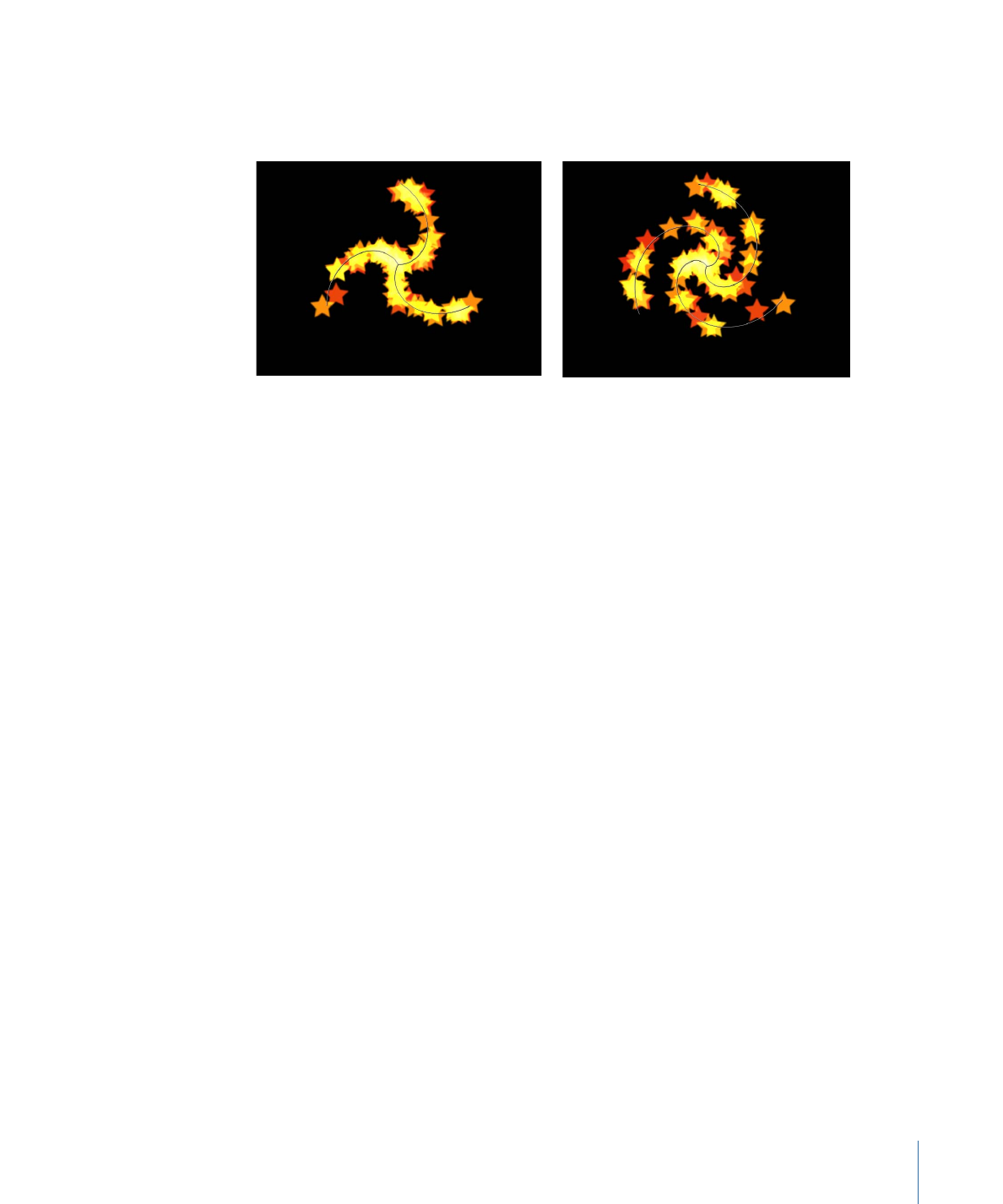
Number of Arms:
This slider, available when Burst or Spiral is chosen in the Shape pop-up
menu, defines the number of branches from which particles are emitted. The default
value is 3.
Spiral emitter shape set to default Number of
Arms and Twists
Spiral emitter shape with default Arms and
Twists set to .70
Amplitude:
This slider, available when Wave is chosen in the Shape pop-up menu, defines
half the distance from the highest point to the lowest point in the wave. Higher values
result in more extreme waves.
Frequency:
This slider, available when Wave is chosen in the Shape pop-up menu, defines
the number of waves. Higher values result in more waves.
Phase:
This dial, available when Wave is chosen in the Shape pop-up menu, defines the
degrees of the offset of the waves from the start and end points of the path. When set
to 0 degrees (default), the wave begins and ends at half the distance from the highest
point to the lowest point in the wave. When set to 90 degrees, the wave begins and ends
at the highest point in the wave. When set to 90 degrees, the wave begins at the lowest
point in the wave. When set to 180 degrees, the waves are the same as 0 degrees, but
inverted.
Damping:
This slider, available when Wave is chosen in the Shape pop-up menu,
determines the direction of progressive diminishment of the oscillation of the wave.
Positive damping values diminish the wave forward (from left to right); negative values
diminish the wave backward (from right to left).
Offset:
This slider becomes available when any of the following is chosen in the Shape
pop-up menu: Line, Rectangle (with Arrangement set to Outline), Circle (with Arrangement
set to Outline), Burst, Spiral, Wave, Geometry, or Image. This parameter offsets the emitter
itself or the particles generated on the shape. For example, when the emitter Shape is a
Line, changing the Offset value moves the emitter’s position in the Canvas. When the
emitter Shape is a Rectangle and Pattern is set to Outline, changing the Offset value
moves the particles along the edge of the shape.
701
Chapter 14
Working with Particles

3D:
When this checkbox is selected, the 3D emitter shapes (Box and Sphere) become
available. Because all emitter shapes can be used in 3D space, additional 3D parameters
are available for all emitter shapes when the 3D checkbox is selected: Render Particles,
Emission Latitude, and Emission Longitude. These additional parameters appear in the
Emitter Inspector and HUD.
These parameters are available for all shapes, regardless of the Arrangement setting.
Note: When the 3D checkbox is selected, particles cannot receive reflections, and the
Reflections parameter (in the Properties Inspector) is no longer available for the emitter.
Additionally, when the 3D checkbox is selected, In Global 3D (Better) must be selected
from the Render Particles pop-up menu for particles to cast shadows and to be affected
by lights.
For more information on the additional 3D controls in the HUD, see
Emitter HUD
Parameters
.
Emission Angle:
This dial, available when the Shape pop-up menu is set to a 2D shape,
sets the direction in which particles travel. This parameter works in conjunction with the
Emission Range parameter. It is equivalent to one of the functions of the graphical emission
control in the Emitter HUD.
Note: When using an emitter shape other than a Point, such as a Line, Circle, Rectangle,
Spiral, Burst, or Wave, and Outline is chosen from the Arrangement pop-up menu, setting
the Emission Angle parameter to 180 degrees and the Emission Range parameter to
0 degrees restricts the emission of particles to the inside of the shape. Setting the Emission
Angle parameter to 0 degrees and the Emission Range parameter to 0 degrees restricts
the emission of the particles to outside of the shape.
Emission Range:
A dial that restricts the area around the center of each emission point
where particles are generated, in the direction of the Emission Angle. It is equivalent to
one of the functions of the graphical emission control in the Emitter HUD.
Note: When using a Line, Circle, Rectangle, Spiral, Burst, or Wave (but not Geometry)
shape, setting the Emission Range parameter to 0 degrees keeps particles perpendicular
to the emitter when they emerge.
Render Particles:
A pop-up menu that appears when the 3D checkbox is selected, enabling
you to choose between two rendering methods for the particles:
• In Local 3D (Faster): The default setting, renders particles faster but does not allow for
intersections with layers in the particles group or with layers in other groups. Nor does
it allow particles to cast shadows.
• In Global 3D (Better): This setting allows the particles to intersect with layers in the
emitter group and with layers in other groups. When turned on, your project’s playback
performance is slowed.
702
Chapter 14
Working with Particles
Important:
When the 3D checkbox is selected, In Global 3D (Better) must be selected
from the Render Particles pop-up menu for the 3D particles to cast shadows and to be
affected by lights.
Emission Latitude:
Available when the 3D checkbox is selected, this dial specifies the
emission direction (in degrees latitude) of the particles.
Emission Longitude:
Available when the 3D checkbox is selected, this dial specifies the
axis of rotation (in degrees longitude) from which the particles are emitted.
Depth Ordered:
This checkbox becomes available when the 3D checkbox is selected.
With Depth Ordered deselected, particle distribution is completely random, regardless
of size. The result is the possibility of particle arrangements appearing to violate the rules
of perspective.
703
Chapter 14
Working with Particles
When selected, this checkbox draws the particles in the particle system according to each
particle’s actual 3D position in the project. In other words, particles closer to the camera
appear closer; particles farther from the camera appear more distant.
Render Order:
A pop-up menu that determines whether new particles are drawn on top
of or underneath particles that have already been generated. There are two options:
• Oldest First: New particles appear on top of older particles.
• Oldest Last: New particles appear underneath older particles.
Interleave Particles:
Selecting this checkbox mixes particles generated from multiple
cells together. Deselecting this checkbox layers particles in the same order as the cells
that generate them.
Note: This option has no effect with particle systems containing only one cell. Leaving
this option off speeds rendering with multiple cells.
Face Camera:
This checkbox, available when 3D is enabled, forces the particle system to
face the active scene camera. For more information on cameras, see
Active Camera
.
704
Chapter 14
Working with Particles