Replicator Controls in the Inspector
The controls in the Replicator Inspector give you complete control over every aspect of
the pattern created by the selected replicator. This includes the shape upon which the
pattern is built and the shape’s related parameters, such as the size of the pattern, how
the elements are arranged in the pattern, and so on.
Shape:
The Shape pop-up menu sets the overall shape of the onscreen replicator pattern.
The default setting is Rectangle. Choose any of up to ten shape styles from the menu to
alter the distribution of the pattern elements.
755
Chapter 15
Using the Replicator
Note: Depending on the item you choose in the Shape pop-up menu, additional controls
may appear in the Replicator Inspector. For example, when Rectangle is selected in the
Shape pop-up menu, the Outline, Tile Fill, and Random Fill options become available in
the Arrangement pop-up menu. These additional controls let you further customize the
chosen shape.
The Shape pop-up menu contains the following items:
• Line: Elements are positioned on a line. In the Inspector, you can set a specific number
of points on the line—one element is positioned at every point (including the end
points of the line). The Line shape displays additional Start Point, End Point, Points, and
Offset parameters.
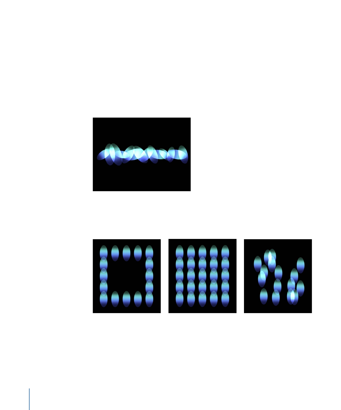
• Rectangle: Elements are positioned in a rectangle along the replicator outline, or in a
tile or random fill pattern. When Rectangle is selected, the Arrangement parameter
becomes available. Depending on the selected Arrangement, the Rectangle shape
displays additional parameters.
Rectangle shape with
Arrangement set to Outline
Rectangle shape with
Arrangement set to Tile Fill
Rectangle shape with
Arrangement set to Random Fill
756
Chapter 15
Using the Replicator
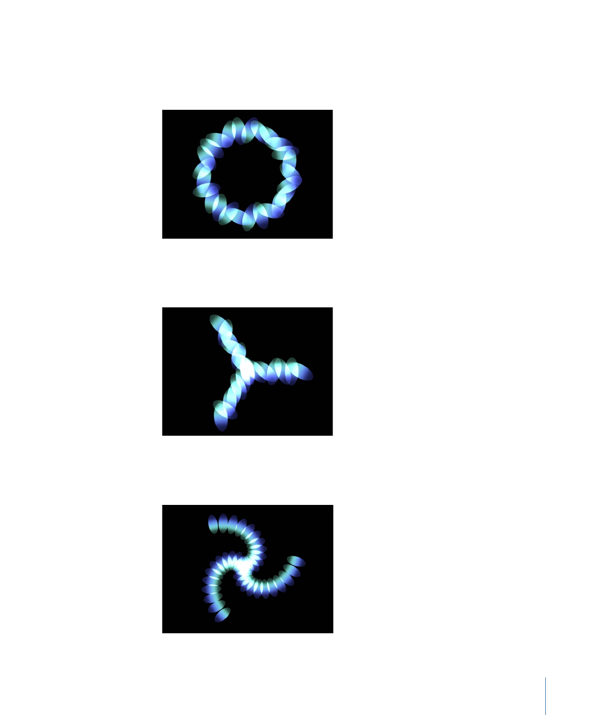
• Circle: Elements are positioned in a circle along the replicator outline, or in a tile or
random fill pattern. When Circle is selected, the Arrangement parameter becomes
available. Depending on the selected Arrangement, the Circle shape displays additional
parameters. In the following image, the circle’s Arrangement is set to Outline.
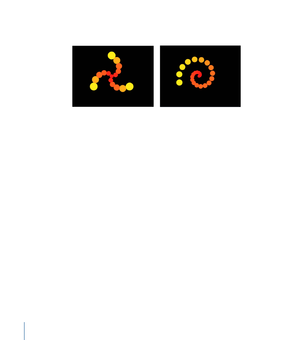
• Burst: Elements are positioned in a flare pattern. The Burst shape displays additional
Radius, Number of Arms, Points Per Arm, Offset, and Origin parameters in the Replicator
Inspector.
• Spiral: Elements are positioned in a spiral pattern. The Spiral shape displays additional
Radius, Twists, Number of Arms, Points Per Arm, and Offset parameters in the Replicator
Inspector.
757
Chapter 15
Using the Replicator
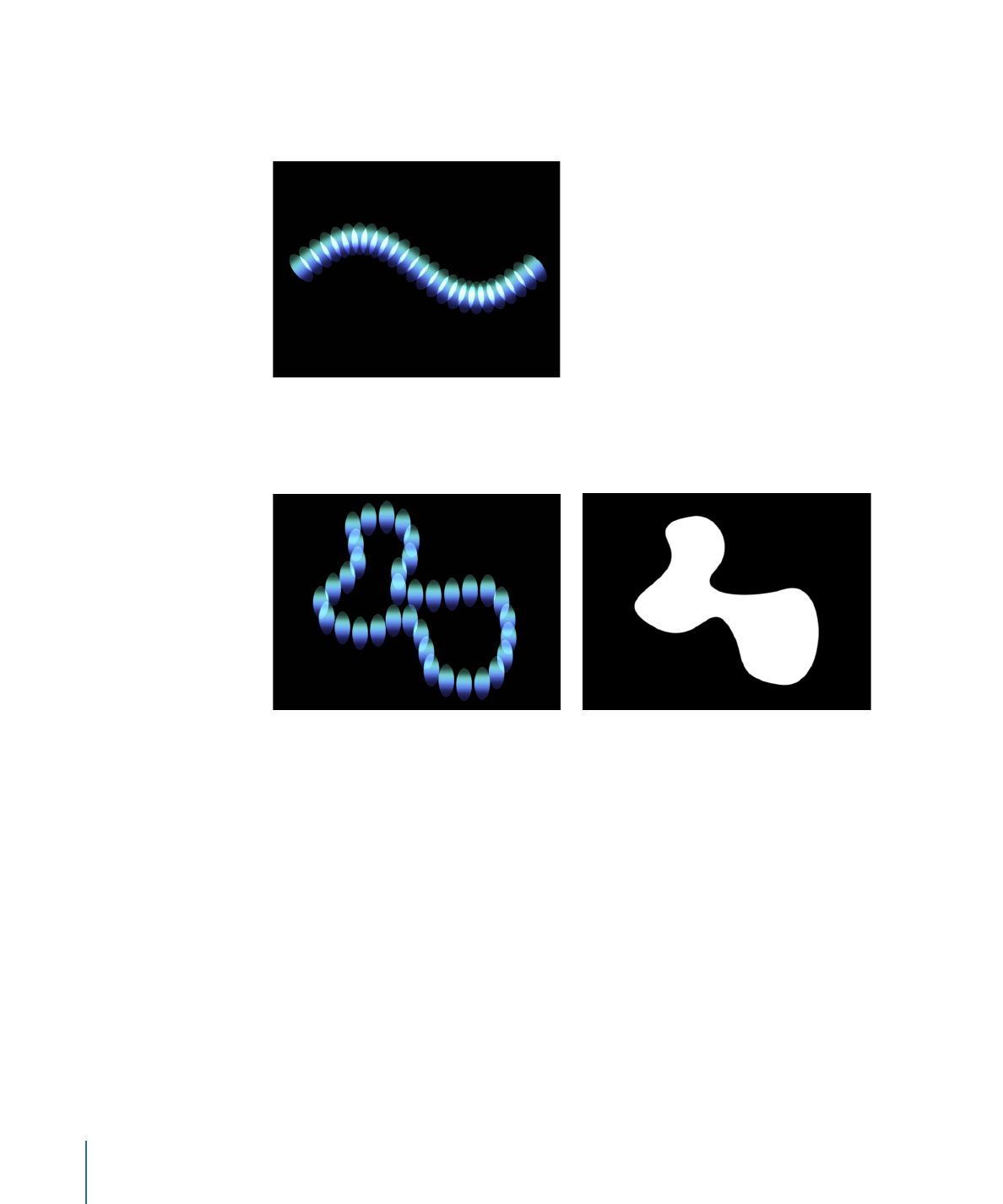
• Wave: Elements are positioned on a waveform. The Wave shape displays additional
Start and End Point, Amplitude, Frequency, Phase, Damping, Points, and Offset
parameters in the Replicator Inspector.
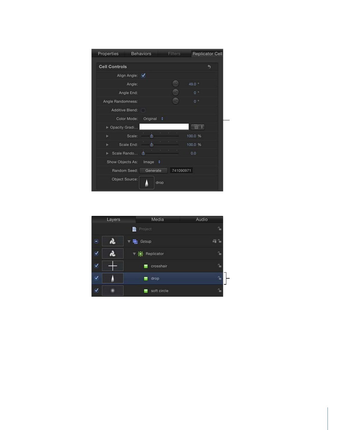
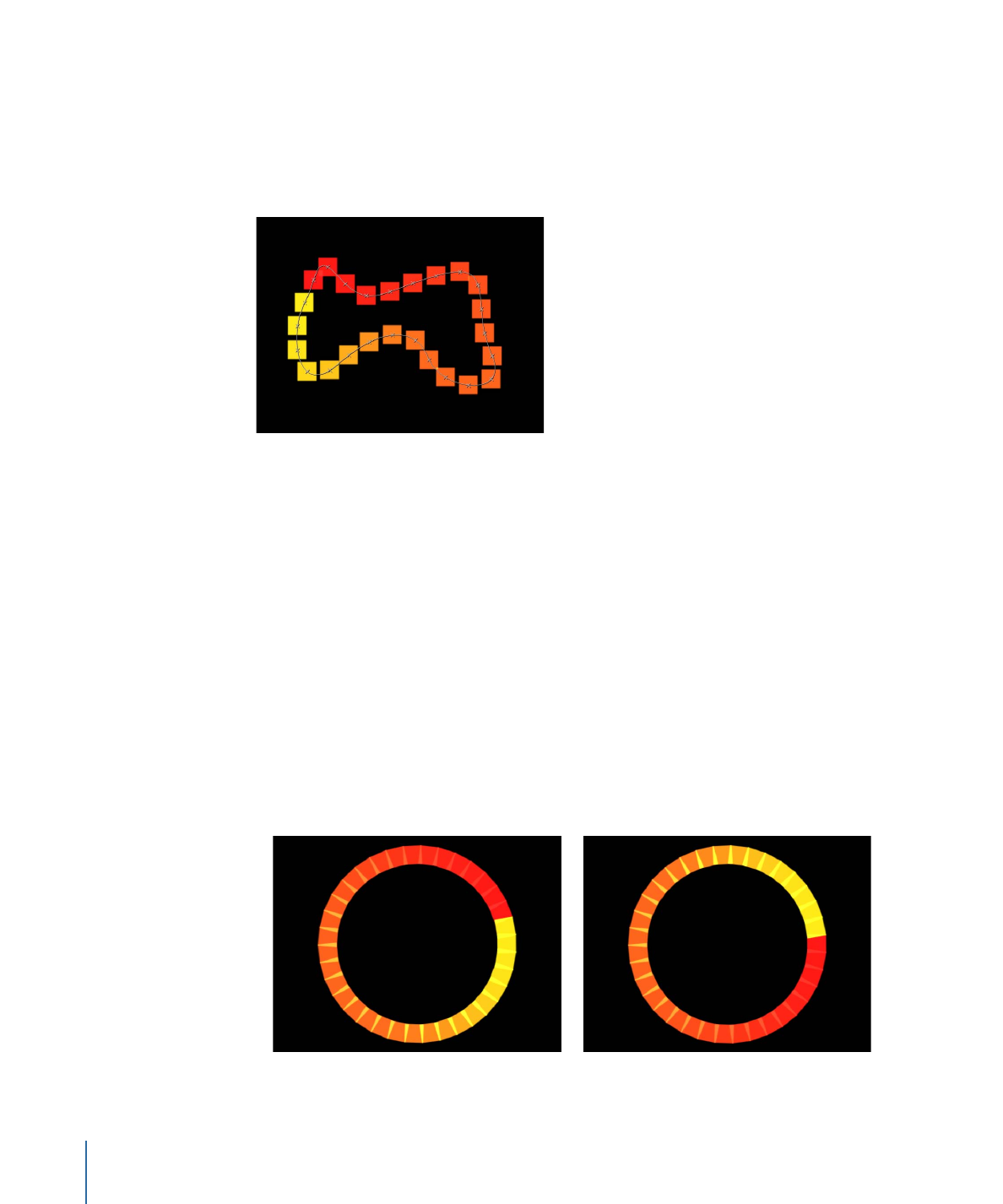
• Geometry: Elements are positioned along the edge of a shape, defined by a spline
object used as the shape source. The Geometry shape displays additional Shape Source,
Points, and Offset parameters in the Replicator Inspector.
Cells along the edge of the object defined in
the Shape Source image well
Object used as the Shape Source
For information on using geometry (a shape) as a replicator shape, see
Replicator Cell
Controls in the Inspector
.
• Image: Elements appear within an area defined by an image or along its border,
depending on what is chosen from the Arrangement pop-up menu. The image may
have an alpha channel. If so, the shape of the alpha channel can also be used to define
the pattern. When Image is selected, the Arrangement parameter becomes available.
Depending on the selected Arrangement, the Image shape displays additional
parameters.
For information on using an image as a replicator shape, see
Using Image and Geometry
Objects
.
758
Chapter 15
Using the Replicator
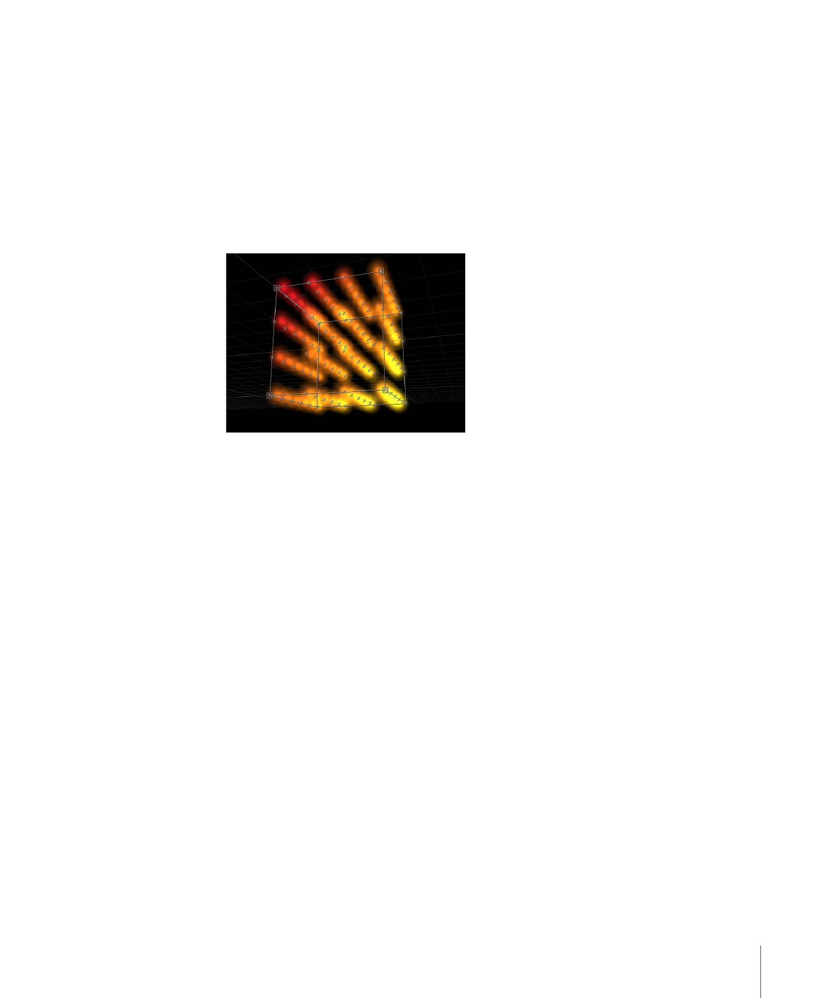
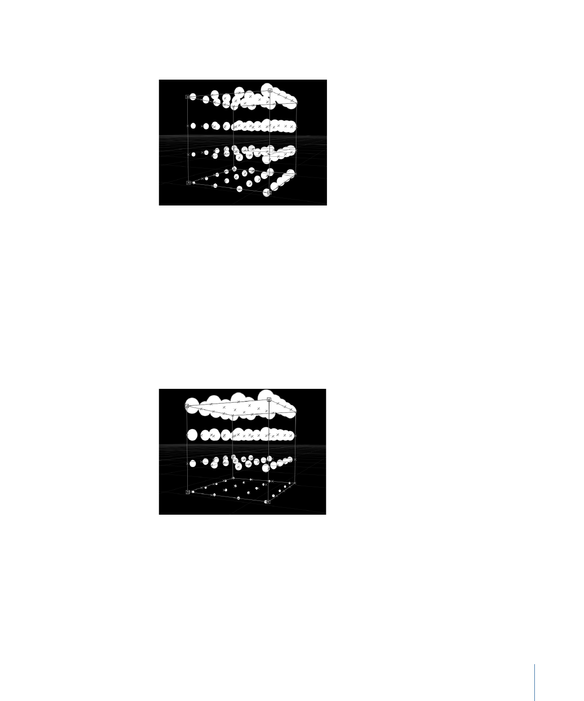
• Box: This option is available when the 3D checkbox is selected in the Replicator
Inspector. Elements are positioned in a three-dimensional cube along the replicator
outline, or on its surface in a tile or random fill pattern. Using the onscreen controls
(with the Adjust Item tool), you can specify the size and location of the rectangle. Drag
the front horizontal edge to adjust height; drag the front vertical edge to adjust width;
drag a back edge to adjust depth; drag a front corner to simultaneously adjust the
width and height. To reposition the replicator, drag in the replicator (but not on an
edge or corner point). Depending on the selected Arrangement, the Box shape displays
additional parameters. In the following image, the box’s Arrangement is set to Tile.
• Sphere: This option is available when the 3D checkbox is selected in the Replicator
Inspector. Elements are positioned in a three-dimensional sphere along the replicator
outline, or on its surface in a tile or random fill pattern. Using the onscreen controls
(with the Adjust Item tool), you can specify the radius and location of the circle. Drag
the outline of the sphere to adjust its radius; drag in the sphere to reposition it in the
Canvas. When Sphere is selected, the Arrangement parameter becomes available.
Depending on the selected Arrangement, the Sphere shape displays additional
parameters.
Arrangement:
This pop-up menu, available when Shape is set to Rectangle, Circle, Image,
Box, or Sphere, specifies the layout of the elements in the selected shape. The arrangement
options are:
• Outline: Elements are positioned along the edge of the shape.
• Tile Fill: Elements are positioned in a tiled pattern of rows and columns in the circle,
rectangle, image, box, or sphere pattern. You can specify the number of columns and
rows, as well as the Tile Offset.
• Random Fill: Elements are positioned randomly from within circle, sphere, rectangle,
or box.
Size:
This slider is available when Shape is set to Rectangle or Box. Click the disclosure
triangle to display separate Width, Height, and Depth (for the Box shape) parameters.
When Circle is the selected shape, this parameter becomes Radius.
759
Chapter 15
Using the Replicator
Note: For projects using the default camera settings and a default Z position for the
replicator, the Height is measured in pixels; however, the Width is measured in square
pixels. This is done so a shape that is numerically square appears square when “Correct
for Aspect Ratio” is selected in the View pop-up menu in the top-right corner of the
Canvas.
Shape Source:
This image well, which becomes available only when Shape is set to
Geometry, allows you to load a shape object as the source for the replicator pattern. To
set the shape source for the replicator, drag a shape from the Layers list or Timeline to
the Shape Source well.
Image Source:
This image well, which becomes available when the Shape parameter is
set to Image, allows you to load an image object as the source for the replicator shape.
To set the image source, drag an image from the Layers list or Timeline to the Image
Source well.
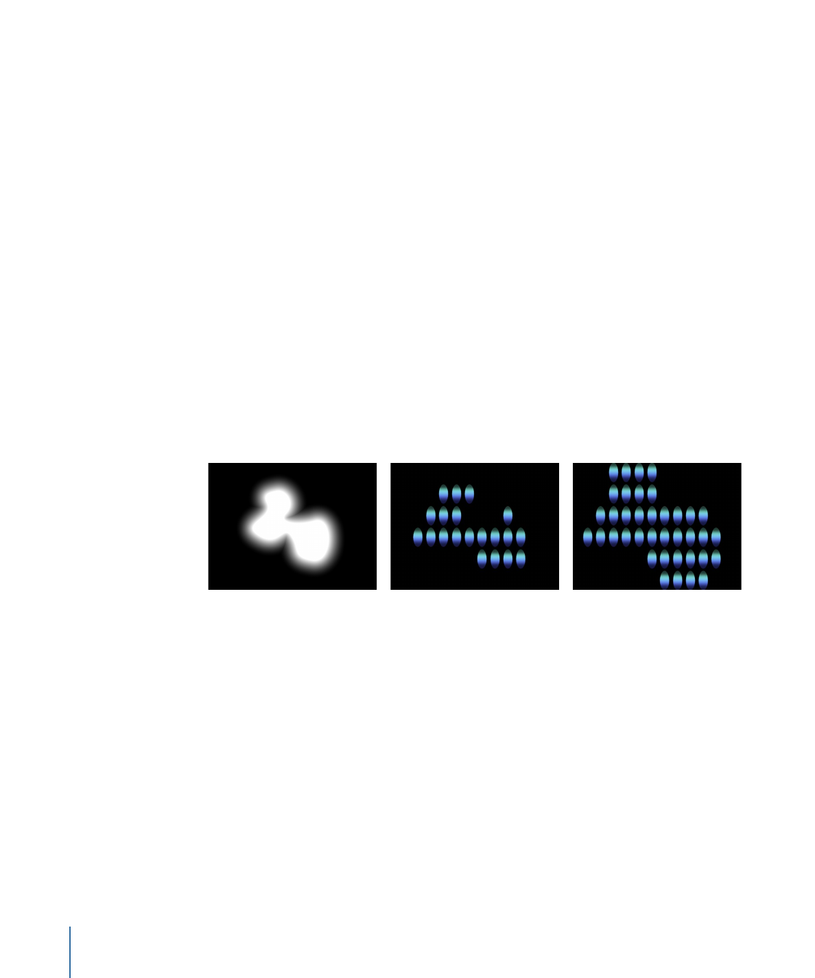
Emission Alpha Cutoff:
When the Image Source object contains an alpha channel, this
slider defines the minimum opacity value necessary to create an element at that point
on the source image. For example, when set to 25%, elements only appear at points
where the alpha value of the image is equal to or greater than 25% opacity. The lower
the Emission Alpha Cutoff value, the more cells appear. For this parameter to be effective,
the alpha channel must have areas of varying transparency.
Shape with a feathered edge used
as Image Source
Emission Alpha Cutoff set to 75%
Emission Alpha Cutoff set to 30%
Start Point:
This parameter is available when Shape is set to Line or Wave. Two value
sliders define, in X, Y, and Z coordinates, the first point of the line or wave on which the
elements are positioned. Click the disclosure triangle to access the Z Start Point value
slider. You can adjust these values in the Canvas using the onscreen controls (with the
Adjust Item tool).
End Point:
This parameter is available when Shape is set to Line or Wave. Two value
sliders define, in X, Y, and Z coordinates, the second point of the line or wave on which
the elements are positioned. Click the disclosure triangle to access the Z Start Point value
slider. You can adjust these values in the Canvas using the onscreen controls (with the
Adjust Item tool).
760
Chapter 15
Using the Replicator
Amplitude:
This slider, available only when Shape is set to Wave, defines half the distance
from the highest point to the lowest point in the wave. Higher values result in more
extreme waves.
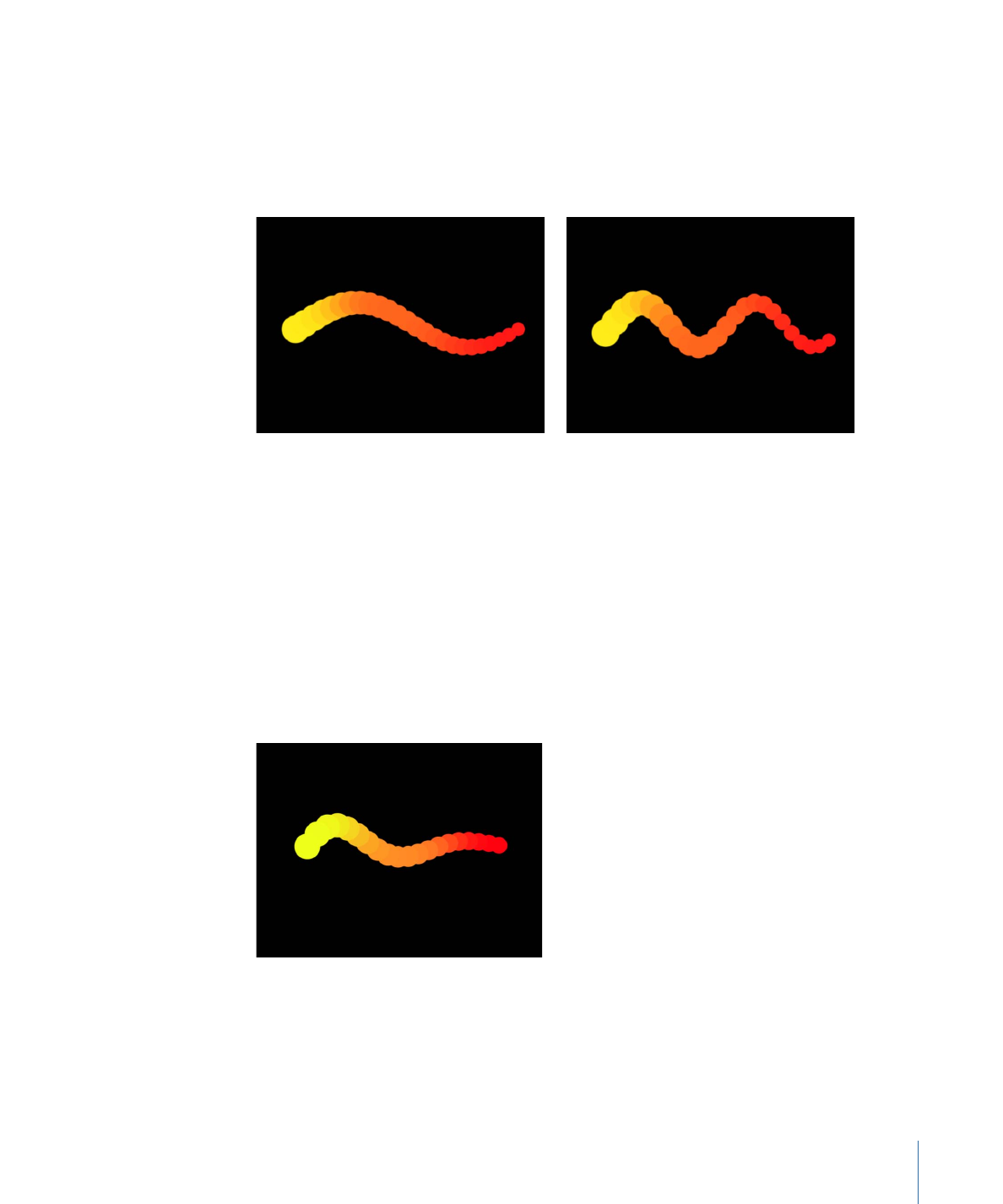
Frequency:
This slider, available only when Shape is set to Wave, defines the number of
waves. The default is value is 1.
Default Frequency value (1)
Frequency value set to 2
Phase:
This slider, available only when Shape is set to Wave. A dial defines the degree of
offset of the waves from the start and end points of the path. When set to 0 degrees
(default), the wave begins and ends at half the distance from the highest point to the
lowest point in the wave. When set to 90 degrees, the wave begins and ends at the
highest point in the wave. When set to –90 degrees, the wave begins at the lowest point
in the wave. When set to 180 degrees, the waves are the same as 0 degrees, but inverted.
Damping:
This slider, available only when Shape is set to Wave, progressively diminishes
the oscillation of the wave. Positive damping values diminish the wave forward (from left
to right); negative values diminish the wave backward (from right to left).
Points:
When Shape is set to Rectangle, Circle, Image, Box, or Sphere, and Arrangement
is set to Outline or Random Fill, this slider specifies the number of evenly distributed
element points along the edge of the shape.
761
Chapter 15
Using the Replicator
When Shape is set to Line or Wave, the slider sets the number of evenly distributed
element points on the line or wave. When the Adjust Item tool is selected, the points are
visible in the Canvas.
When Shape is set to Geometry, the slider sets the number of evenly distributed element
points around the shape.
Offset:
When Shape is set to Line or Wave, adjusting this slider moves the elements along
the line or wave.
When Shape is set to Rectangle, Circle, Image, Box, or Sphere, and Arrangement is set to
Outline, adjusting this slider moves the elements along the edge of the shape.
When Shape is set to Geometry, adjusting this slider moves the position of the elements
along the edge of the shape.
Build Style:
This pop-up menu and its options appear depending upon the selected
Shape and Arrangement. Build Style specifies the how elements are built over the replicator
shape.
For Rectangle, Circle, and Image replicator shapes with Arrangement set to Outline, or
for a Geometry shape, the Build Style options are:
• Clockwise: Places the elements along the shape in a clockwise direction.
• Counter Clockwise: Places the elements along the shape in a counterclockwise direction.
Build Style set to Clockwise
Build Style set to Counter Clockwise
762
Chapter 15
Using the Replicator

For Rectangle and Image shapes with Arrangement set to Tile Fill and Origin set to
Upper Left, Upper Right, Lower Left, or Lower Right, the Build Style options are:
• Across: Builds the elements across the pattern in the direction implied by the Origin
parameter.
• By Row: Builds the elements over the pattern by row.
• By Column: Builds the elements over the pattern by column.
For Box shapes with the Arrangement set to Tile Fill and Origin set to Front Upper Left,
Front Upper Right, Front Lower Left, Front Lower Right, Back Upper Left, Back Upper
Right, Back Lower Left, or Back Lower Right, the Build Style options are:
• Across: Builds the elements across the pattern in the direction implied by the Origin
parameter.
• By Row, Column, Rank: Builds the elements over the pattern by row, column, then
rank starting from the Origin.
• By Column, Row, Rank: Builds the elements over the pattern by column, row, then
rank starting from the Origin.
• By Row, Rank, Column: Builds the elements over the pattern by row, rank, then column
starting from the Origin.
• By Column, Rank, Row: Builds the elements over the pattern by column, rank, then
row starting from the Origin.
• By Rank, Row, Column: Builds the elements over the pattern by rank, row, then column
starting from the Origin.
• By Rank, Column, Row: Builds the elements over the pattern by rank, column, then
row starting from the Origin.
Radius:
This slider, available when Shape is set to Burst, Spiral, Circle, or Sphere, defines
the size of the selected shape.
763
Chapter 15
Using the Replicator
Twists:
This slider, available only when Shape is set to Spiral, defines the number of turns
in a spiral. The default value is 0.25. When Number of Arms is set to one, a single spiral
is created.
Spiral with default parameter settings
Spiral with Number of Arms set to 1
Number of Arms:
This slider, available only when Shape is set to Burst or Spiral, defines
the number of branches on which the elements are positioned. The default value is 3.
Points Per Arm:
This slider, available only when Shape is set to Burst or Spiral, defines
the number of element points on each branch of the burst or spiral. When the Adjust
Item tool is selected, the points are visible in the Canvas.
Columns:
This slider, available when Shape is set to Rectangle, Circle, or Image (with
Arrangement set to Tile Fill), or when Shape is set to Box or Sphere (with Arrangement
set to Outline or Tile Fill), specifies the number of vertical columns (or horizontal element
points) on a grid over the selected replicator. In the case of an irregular shape
(nonrectangular), points that fall outside the shape are ignored.
Rows:
This slider, available when the Arrangement parameter is set to Tile Fill, specifies
the number of horizontal rows (or vertical element points) on a grid over the selected
replicator. In the case of an irregular shape (nonrectangular), points that fall outside the
shape are ignored. This control is also available for Box and Sphere when Arrangement
is set to Outline or Tile Fill.
Ranks:
This slider, available when Shape is set to Box (with Arrangement set to Tile Fill
or Outline), or Sphere (with Arrangement set to Tile Fill), specifies the number of points
in Z space on a grid over the selected replicator. In the case of an irregular shape
(nonrectangular), points that fall outside the shape are ignored.
764
Chapter 15
Using the Replicator
Tile Offset:
This slider, available when Shape is set to Rectangle, Circle, Image, Box, or
Sphere, and Arrangement is set to Tile Fill, specifies the amount (in percentage points)
that the elements are offset from the pattern. Values from 0 to 100% offset the rows
toward the right, and values from 0 to –100% offset the rows toward the left. A value of
50 or –50% creates a brickwork pattern.
Rectangle shape set to Tile Fill
Tile Offset set to a value of 20%
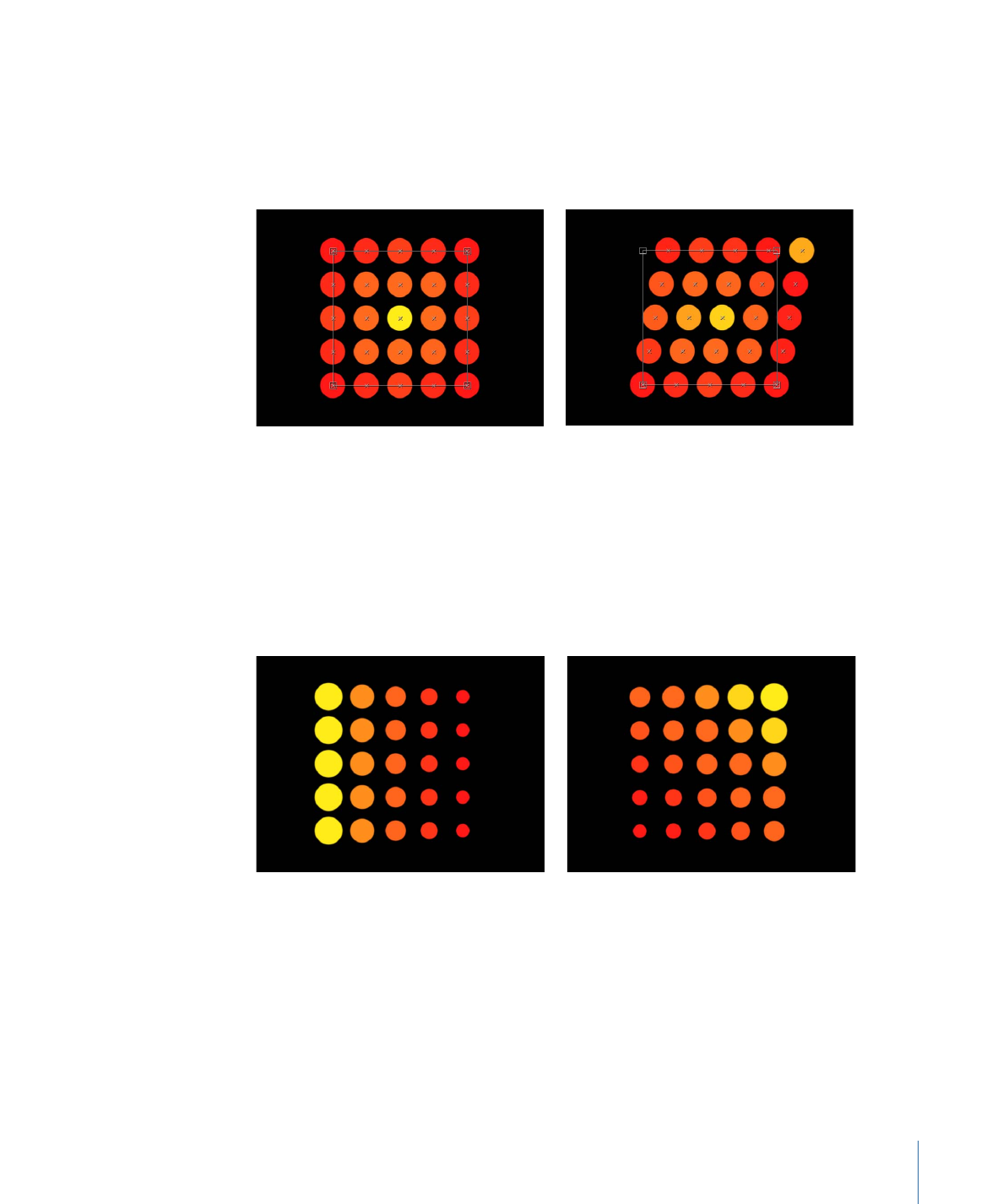
Origin:
This pop-up menu, available when Shape is set to Rectangle, Circle, Image, Box,
or Sphere, and Arrangement is set to Tile Fill or Random Fill, specifies how the elements
traverse across the pattern from a point of origin. For example, when set to Left, the
elements sweep across the pattern from left to right. When set to Upper Right, the
elements traverse from the upper-right corner point of the shape to the lower-right
corner.
Origin set to Left
Origin set to Upper Right
The Origin pop-up menu contains the following items:
• Upper Left: The elements originate in the upper-left corner of the pattern and end in
the lower-right corner.
• Upper Right: The elements originate in the upper-right corner of the pattern and end
in the lower-left corner.
765
Chapter 15
Using the Replicator

• Lower Left: The elements originate in the lower-left corner of the pattern and end in
the upper-right corner.
• Lower Right: The elements originate in the lower-right corner of the pattern and end
in the upper-left corner.
• Center: The elements originate in the center of the pattern and move outward. This is
the default Origin option.
• Left: The elements originate at the left side of the pattern and end at the right side.
• Right: The elements originate at the right side of the pattern and end at the left side.
• Top: The elements originate at the top of the pattern and end at the bottom.
• Bottom: The elements originate at the bottom of the pattern and end at the top.
When Circle or Sphere is chosen from the Shape pop-up menu and Arrangement is set
to Tile Fill or Random Fill, the Origin options are:
• Center: The elements originate in the center of the pattern and build outward. This is
the default Origin option.
• Edge: The elements originate along the edge of the pattern and build inward.
When Box is chosen from the Shape pop-up menu and Arrangement is set to Tile Fill or
Random Fill, the Origin options are:
• Front Upper Left: The elements originate in the front upper-left corner of the pattern
and end in the back lower right.
• Front Upper Right: The elements originate in the front upper-right corner of the pattern
and end in the back lower left.
• Front Lower Left: The elements originate in the front lower-left corner of the pattern
and end in the back upper right.
• Front Lower Right: The elements originate in the front lower-right corner of the pattern
and end in the back upper left.
• Back Upper Left: The elements originate in the back upper-left corner of the pattern
and end in the front lower right.
766
Chapter 15
Using the Replicator
• Back Upper Right: The elements originate in the back upper-right corner of the pattern
and end in the front lower left.
• Back Lower Left: The elements originate in the back lower-left corner of the pattern
and end in the front upper-right.
• Back Lower Right: The elements originate in the back lower-right corner of the pattern
and end in the front upper-left.
• Left: The elements originate at the left side of the pattern and end at the right side.
The pattern is identical on each row.
• Right: The elements originate at the right side of the pattern and end at the left side.
The pattern is identical on each row.
• Top: The elements originate at the top of the pattern and end at the bottom. The
pattern is identical on each rank.
• Bottom: The elements originate at the bottom of the pattern and end at the top. The
pattern is identical on each rank.
• Front: The elements originate at the front of the pattern and end at the back. The
pattern is identical on each column.
• Back: The elements originate at the back of the pattern and end at the front. The pattern
is identical on each column.
767
Chapter 15
Using the Replicator
• Center: The elements originate in the center of the pattern and move outward. This is
the default Origin option.
• X Axis: The elements originate along the X axis of the pattern and move outward.
• Y Axis: The elements originate along the Y axis of the pattern and move outward.
• Z Axis: The elements originate along the Z axis of the pattern and move outward.
Note: The origin parameter also determines where the Sequence Replicator behavior
starts its animation. For more information on the Sequence Replicator behavior, see
Using
the Sequence Replicator Behavior
.
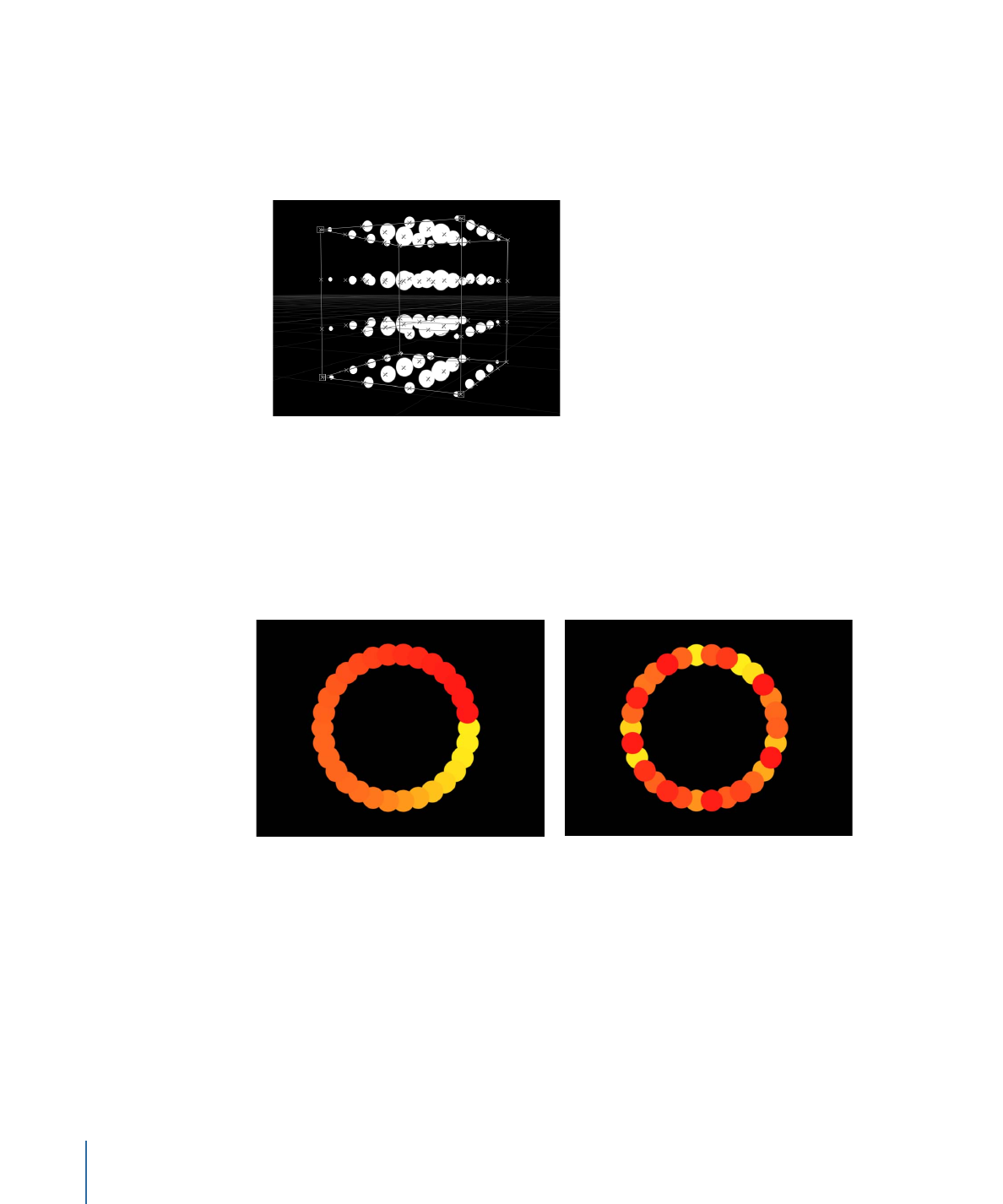
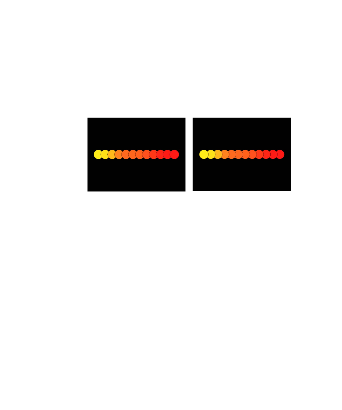
Shuffle Order:
A checkbox that, when selected, rearranges the order in which the elements
appear. When Shuffle Order is selected, the Replicate Seed parameter becomes available.
Pattern with Shuffle Order disabled
Pattern with Shuffle Order enabled
Replicate Seed:
This parameter, available when Shape is set to Rectangle, Circle, Image,
Box, or Sphere, and Arrangement is set to Random Fill, modifies the Random Fill pattern.
Click the Generate button to set a new random seed number.
768
Chapter 15
Using the Replicator
Although the result of the Random Fill option from the Arrangement pop-up menu seems
random, it’s deterministic. This means that the random variation in the pattern is created
based on the number shown. Unless this seed number is changed, a replicator with the
same parameter settings and source object always appears the same. If you don’t like
the current random fill, you can change the seed number by typing a new number or
clicking Generate. This changes the random calculations performed for that pattern. This
parameter is also used to randomize the Shuffle Order parameter.
3D:
Select this checkbox to add the Box and Sphere shapes to the Shape pop-up menu.
Reverse Stacking:
A checkbox that, when selected, inverts the order in which elements
are stacked. To see the effect of this parameter, elements must be overlapping.
Pattern with Reorder disabled: The element to
the right overlaps the next cell to the left.
Pattern with Reorder enabled: The element to
the left overlaps the next cell to the right.
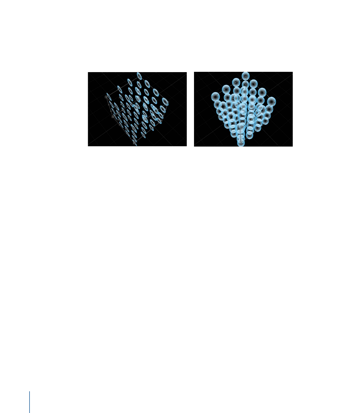
Face Camera:
When this checkbox is selected, the pattern elements actively face the
camera when the camera or the replicator is rotated. When Face Camera is deselected,
the elements face forward in the replicator pattern and appear flat (unless the source
layer or pattern elements are rotated in 3D space). Because Motion only supports 2D
objects, this option is key to giving 2D objects the appearance of 3D as the camera is
animated.
769
Chapter 15
Using the Replicator
Note: Because replicator pattern elements are 2D (flat) objects, the pattern elements are
not visible when you use the orthogonal camera views, such as Left, Right, and Top (unless
the source layer or pattern elements are rotated in 3D space). This is because orthogonal
views are at right angles (perpendicular) to the elements. For more information on using
cameras, see
Cameras
.
Box Replicator with Face Camera turned off
Box Replicator with Face Camera turned on