Replicator Cell Controls in the Inspector
These controls appear at the bottom of the Replicator Inspector (for replicators with a
single cell) or in the Replicator Cell Inspector (for replicators with multiple cells).
770
Chapter 15
Using the Replicator
Align Angle:
When this checkbox is selected, the replicator elements rotate to match
the shape on which they are positioned. This parameter is available for all replicator types
except for the following: Rectangle, Circle, Image, Box, and Sphere shapes with Tile Fill
or Random Fill.
Spiral replicator with Align Angle disabled
Spiral replicator with Align Angle enabled
Angle:
A dial that specifies (in degrees) the rotation of the replicator elements. When
the 3D checkbox is selected in the Replicator Inspector, the default dial modifies the Z
angle. To modify the rotation of the pattern elements on all three axes (X, Y, and Z), click
the disclosure triangle and adjust the X, Y, and Z dials.
When the 3D checkbox is selected, this parameter also displays the Animate pop-up
menu.
• Animate: A pop-up menu that sets the angle interpolation for keyframed animation of
the Angle parameter. There are two choices:
• Use Rotation: The default interpolation method. When the Angle parameter is
keyframed, pattern elements rotate from their start rotation to their final rotation.
Depending on the animation, the elements may twist before reaching their final
orientation (the last keyframed value). For example, if the X, Y, and Z Angle parameters
are animated from 0 degrees to 180 degrees in a project, the elements rotate on all
axes before reaching their final orientation.
• Use Orientation: This alternate interpolation method provides smoother animation
but does not allow multiple revolutions. It interpolates between the pattern elements’
start orientation (first keyframe) and their end orientation (second keyframe).
771
Chapter 15
Using the Replicator
Angle End:
A dial that specifies (in degrees) the rotation of the replicator elements at
the end of the pattern. The angle value of the elements at the end of the pattern equals
the Angle value (start) plus the Angle End value. For example, if Angle is set to 0 degrees
and Angle End set to 90 degrees, the elements are not rotated at all at their origin, and
are rotated by 90 degrees at the end of the pattern.
Line replicator (Origin set to Start Point) with
Angle value of 0 and Angle End set to 0
Line replicator (Origin set to Start Point) with
Angle value of 0 and Angle End set to 90
In a 3D project, using the default dial modifies the Z angle. To modify the rotation of the
pattern elements on all three axes (X, Y, and Z), click the disclosure triangle and adjust
the individual X, Y, and Z dials.
When the 3D checkbox is selected, Angle End also displays the Animate pop-up menu.
• Animate: A pop-up menu that sets the angle interpolation for keyframed animation of
the Angle parameter. There are two choices:
• Use Rotation: This is the default interpolation method. When the Angle End parameter
is keyframed, pattern elements rotate from their start rotation to their final rotation.
Depending on the animation, the elements may twist before reaching their final
orientation (the last keyframed value). For example, if the X, Y, and Z Angle parameters
are animated from 0 degrees to 180 degrees in a project, the elements rotate on all
axes before reaching their final orientation.
• Use Orientation: This alternate interpolation method provides smoother animation
but does not allow multiple revolutions. It interpolates between the pattern elements’
start orientation (first keyframe) and their end orientation (second keyframe).
Angle Randomness:
A dial that defines an amount of variance in the rotation of replicator
elements. A value of 0 results in no variance—all elements have the same rotational value.
A value greater than 0 introduces a variance. The angle for an element is defined by the
Angle and Angle End parameter, plus or minus a random value falling within the Angle
Randomness.
772
Chapter 15
Using the Replicator
In a 3D project, using the default dial or value slider (when the disclosure triangle is
closed), modifies the Z angle. To modify the rotation of the pattern elements on all three
axes (X, Y, and Z), click the disclosure triangle and adjust the X, Y, and Z dials.
When the 3D checkbox is selected, this parameter also displays the Animate pop-up
menu.
• Animate: A pop-up menu that sets the angle interpolation for keyframed animation of
the Angle Randomness parameter. There are two choices:
• Use Rotation: This is the default interpolation method. When the Angle Randomness
parameter is keyframed, pattern elements rotate from their start rotation to their
final rotation. Depending on the animation, the elements may twist before reaching
their final orientation (the last keyframed value). For example, if the X, Y, and Z Angle
parameters are animated from 0 degrees to 180 degrees in a project, the elements
rotate on all axes before reaching their final orientation.
• Use Orientation: This alternate interpolation method provides smoother animation
but does not allow multiple revolutions. It interpolates between the pattern elements’
start orientation (first keyframe) and their end orientation (second keyframe).
Additive Blend:
By default, replicator elements are composited together using the Normal
blend mode. Select this checkbox to composite all overlapping elements using the Additive
blend mode. This blending occurs in addition to the compositing method set in the
Properties Inspector. The result is that the brightness of overlapping objects is intensified.
Color Mode:
This pop-up menu specifies the origin of the color for replicated elements
There are five menu options:
• Original: Elements are created using the original colors from the source layer. When
Original is chosen, the Opacity Gradient editor appears, allowing you to change the
opacity of the replicator elements over the pattern.
• Colorize: Elements are tinted using the color specified in the Color parameter. Additional
Color and Opacity Gradient parameters appear.
773
Chapter 15
Using the Replicator
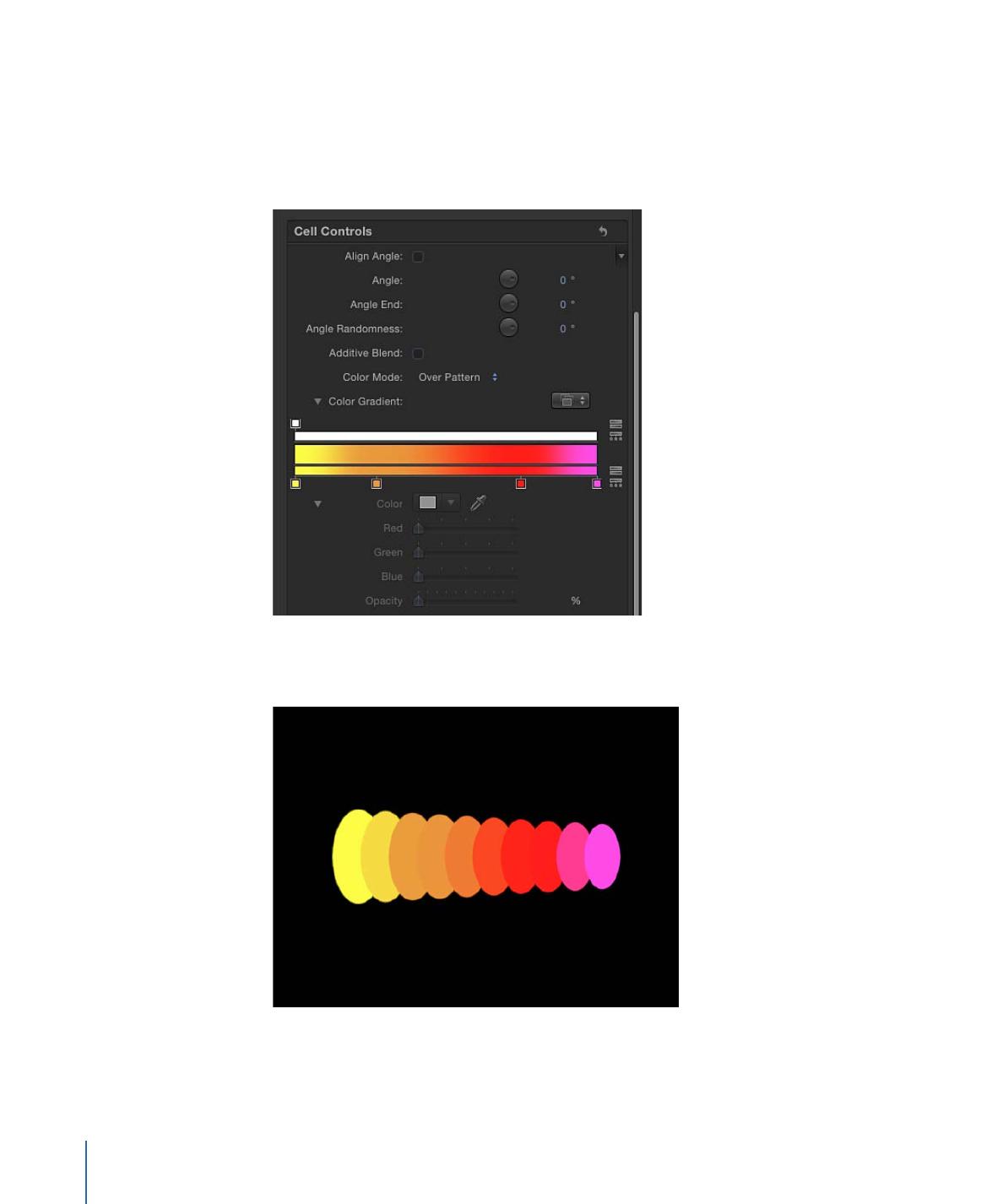
• Over Pattern: Elements are tinted based on how they are ordered in the pattern. When
Over Pattern is chosen, the Color Gradient editor appears, allowing you to define the
range of color of the pattern, beginning with the leftmost color in the gradient, and
progressing through the range of colors until reaching the rightmost color at the end
of the pattern.
Gradual color changes do not appear in each element, but only across the pattern as
a whole. An Opacity control is available at the top of the gradient editor.
774
Chapter 15
Using the Replicator
• Pick From Color Range: Elements are tinted at random, with the range of possible colors
defined by the Color Range gradient editor, which appears when you choose Pick From
Color Range. A point on the gradient is randomly chosen, so the relative sizes of each
color region determine the frequency of the color being used.
For more information on using the gradient controls, see
Using the Gradient Editor
.
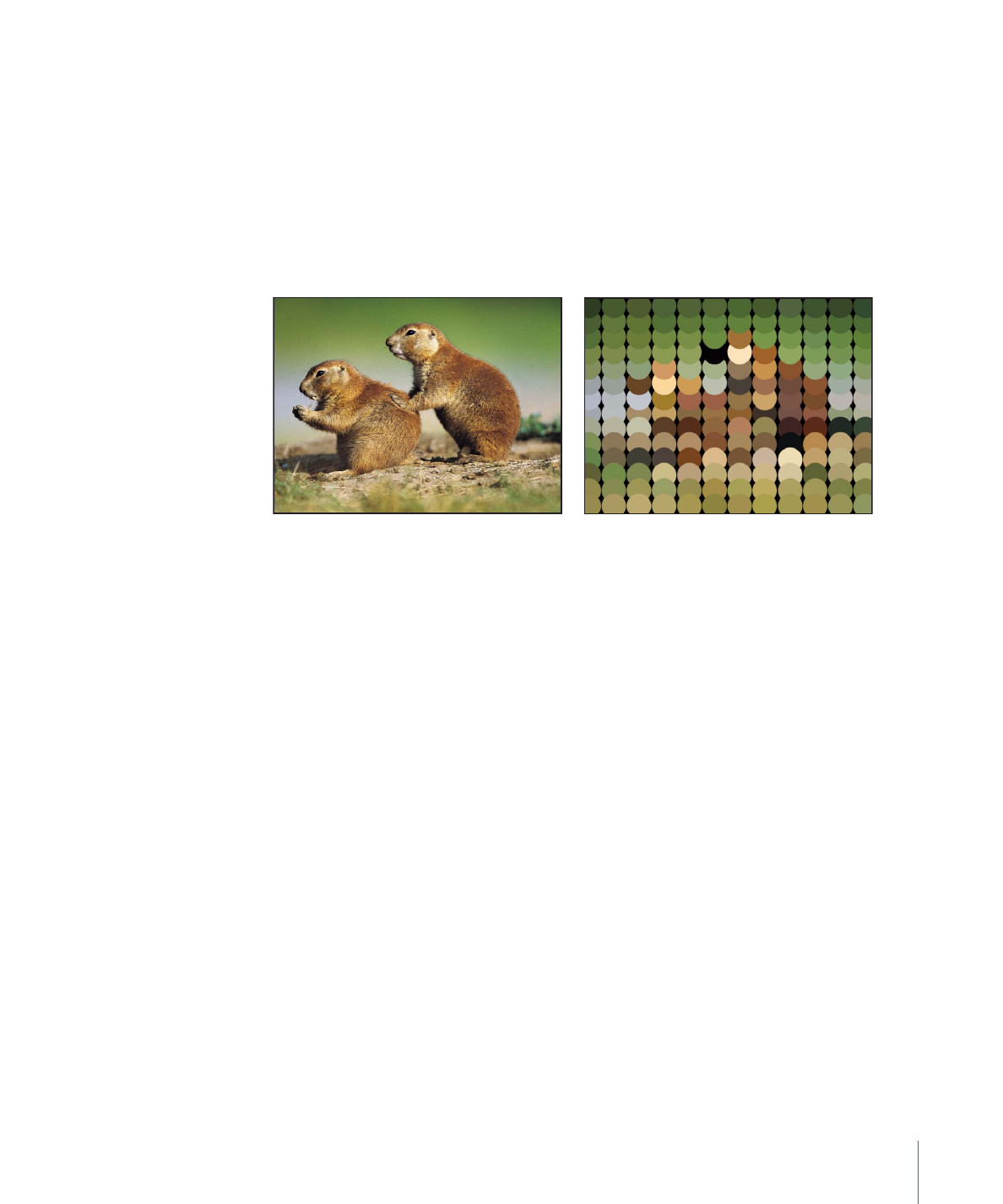
• Take Image Color: Each element’s color is based on the color of the image at the position
of the element point. This mode is only available when an image in used as the replicator
shape.
Color:
This color well becomes available when the Color Mode is set to Colorize. Use it
to specify a color to tint replicator elements. You can also alter each element’s opacity.
This parameter is unique to the cell object. You can click the color well to choose a color,
or open the disclosure triangle and use the Red, Green, Blue, and Opacity channel sliders
or value sliders.
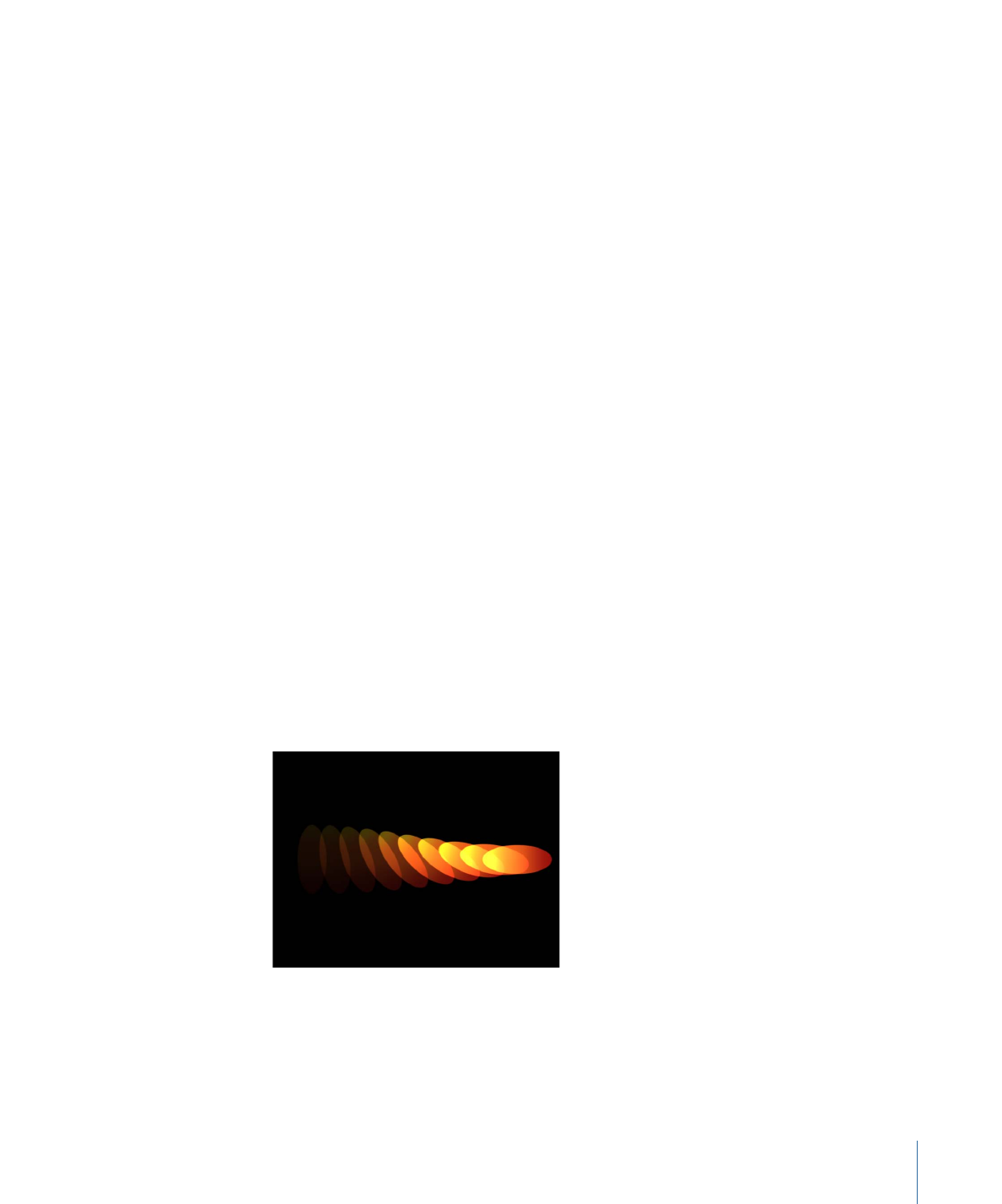
Opacity Gradient:
This gradient editor appears when Color Mode is set to Original or
Colorize. Use it to change the opacity of the replicator elements over the pattern. This
gradient control is limited to grayscale values, which are used to represent varying levels
of transparency. White represents solid elements; progressively darker levels of gray
represent decreasing opacity; and black represents complete transparency. A simple
white to black gradient represents a pattern that is solid at its origin, but which fades out
gradually. For more information on using gradient and opacity gradient controls, see
Using the Gradient Editor
.
Color Repetitions:
When Color Mode is set to Over Pattern, this parameter becomes
available. Drag the slider to increase the number of times the gradient is repeated over
the pattern. For more information on using gradient controls, see
Using the Gradient
Editor
.
Scale:
This slider defines the scale of replicator elements. Click the disclosure triangle
next to the Scale parameter to reveal separate X Scaling and Y Scaling subparameters
that can be used to adjust the width and height of elements separately. By default, Scale
is set to 100%—the size of the replicator elements is equal to the size of the source layer.
775
Chapter 15
Using the Replicator
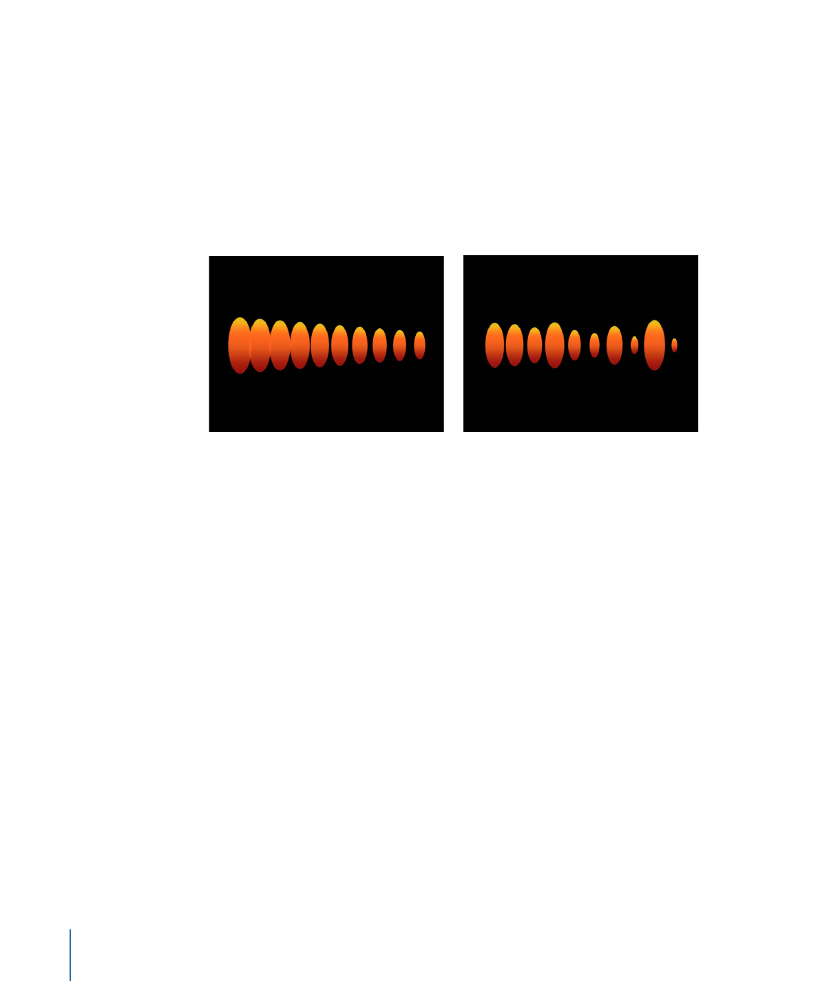
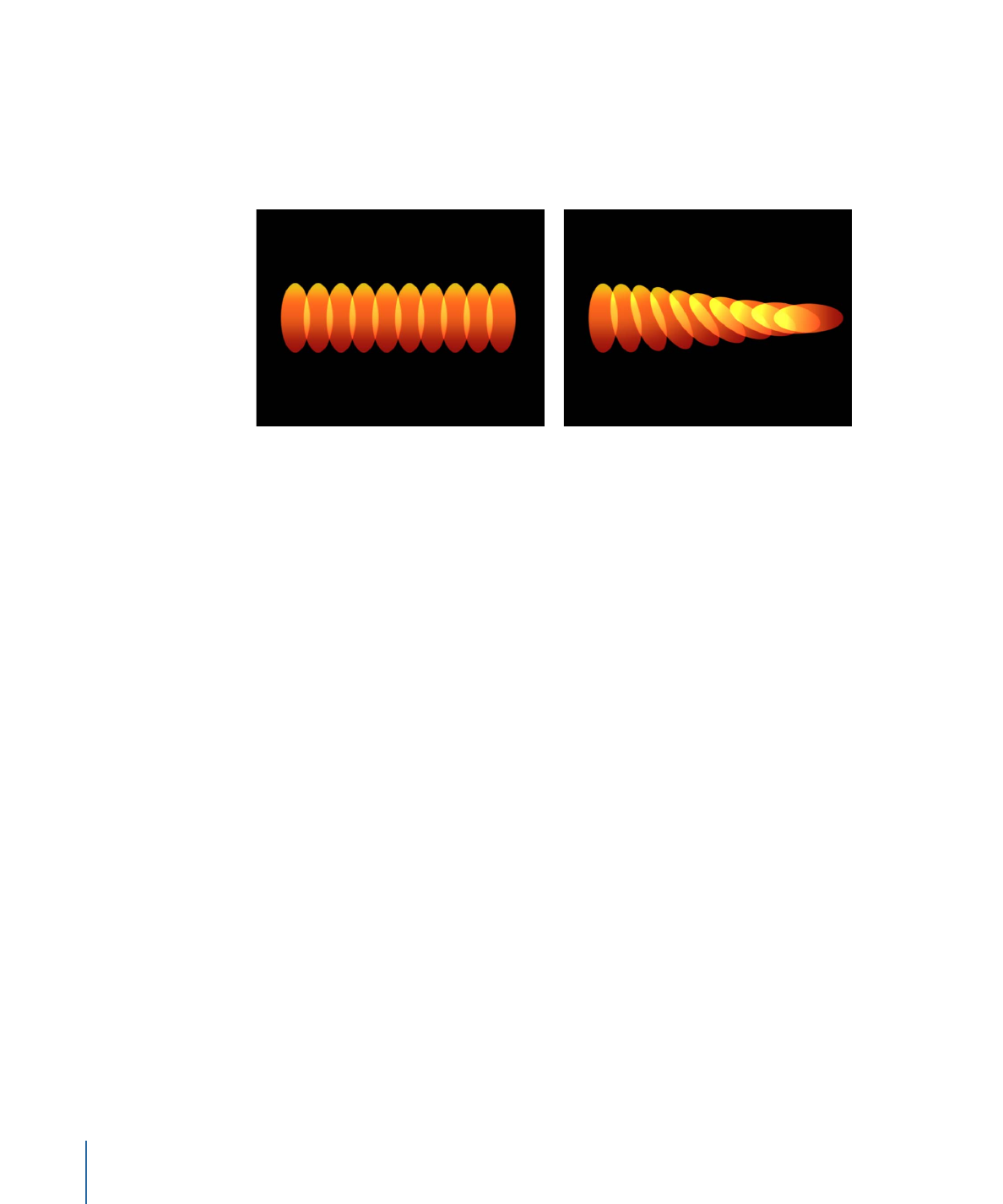
Scale End:
This slider specifies the scale of the replicator elements at the end of the
pattern, relative to the Scale value. For example, if Scale is set to 100% and Scale End set
to 50%, the elements are 100% at their origin and half their size at the end of the pattern.
Scale Randomness:
This slider defines an amount of variance in the scale of replicator
elements. A value of 0 results in no variance—all elements in the pattern are the same
size. A value greater than 0 introduces a variance. The scale for an element is defined by
the Scale parameter, plus or minus a random value falling within the Scale and the Scale
End. The disclosure triangle of the Scale Randomness parameter reveals separate X and
Y subparameters that can be used to set width and height values separately.
Line replicator with Scale set to 100%;
Scale End set to 50%
Scale Randomness set to 75%
Play Frames:
This checkbox appears if the replicator is using a QuickTime object as the
source for a cell. When this checkbox is selected, playback of the animation or movie clip
used for each element will loop. If this checkbox is deselected, the animation or clip is
frozen at the still frame specified by the Random Start Frame parameter or the Source
Start Frame parameter.
Random Start Frame:
This checkbox appears if the replicator is using a QuickTime object
as the source for a cell. Use this control to introduce variation into elements using
QuickTime animation or movies as their source objects. When this checkbox is selected,
each element in the pattern begins at a different frame of the clip. Stills are chosen
randomly if Play Frames is deselected.
Source Start Frame:
This slider appears if the replicator is using a QuickTime object as
the source for a cell. The value selected in the slider designates the start frame of the clip
(when the Play Frames checkbox is selected) or the still frame to display (when Play
Frames is deselected). This parameter appears only if Random Start Frame is deselected.
776
Chapter 15
Using the Replicator
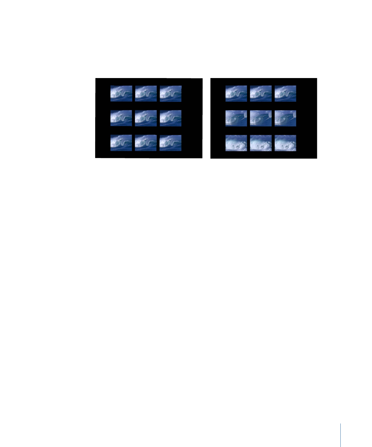
Source Start Frame Offset:
This slider, which appears if the replicator is using a QuickTime
object as the source for a cell, and if Random Start Frame is deselected, offsets the start
frame chosen in the Source Start Frame parameter over the pattern. At their origin, the
elements play the animation from the frame specified in the Source Start Frame parameter.
Each step away from the origin advances the start frame by the offset amount.
Rectangle replicator shape with Origin set to
Top and Source Frame Offset set to 0
When Source Frame Offset is set to 120,
the effect of the offset occurs from the
origin of the cells.
Hold Frames:
This slider appears if the replicator is using a QuickTime object as the source
for a cell. Hold Frames sets the number of times each frame of the source movie is repeated
during playback. The larger the Hold Frames value, the slower your playback.
Hold Frames Randomness:
This slider, which appears if the replicator is using a QuickTime
object as the source for a cell, varies the number of frames to hold.
777
Chapter 15
Using the Replicator
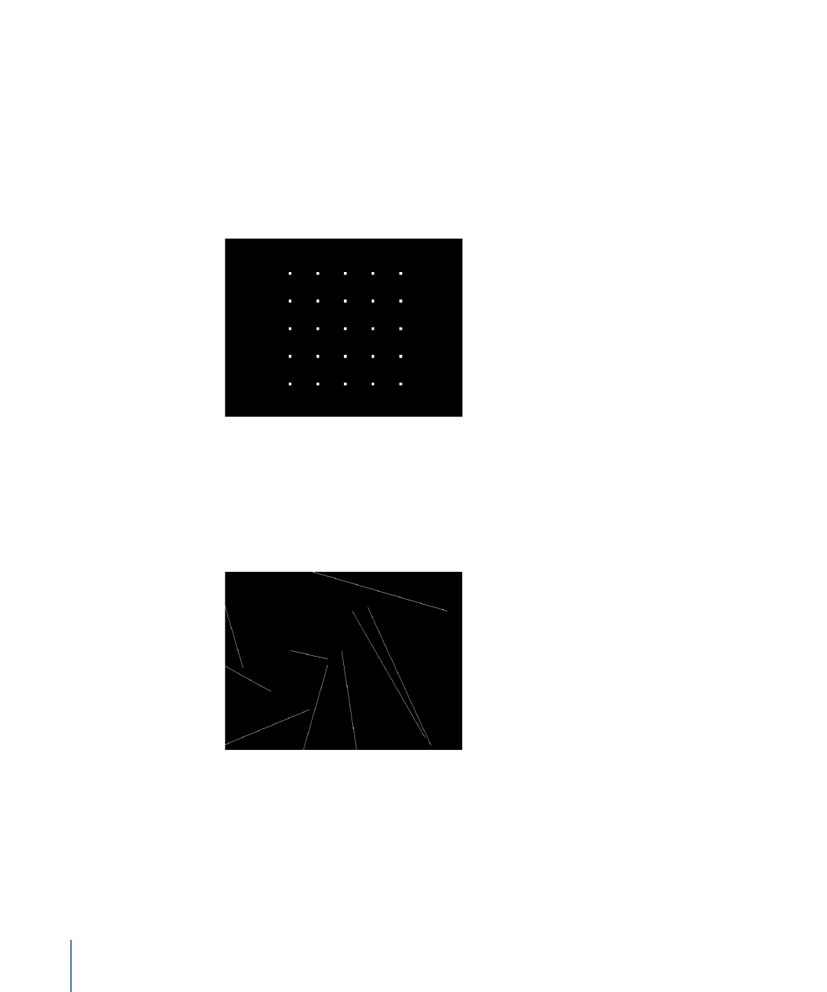
Show Objects As:
Use this pop-up menu to set the display of replicator elements to a
preview mode, or as they actually appear. The nonimage modes play back more efficiently
when viewing a complex replicator pattern. By default, this pop-up menu is set to Image,
which displays each element as it is supposed to appear. Choose one of the following
four options:
• Points: Each element is represented by a single point. This is the fastest preview mode.
When you choose Points, the Point Size slider appears, allowing you to increase the
size of the points for easier viewing. In the following image, the Point Size is set to 8.
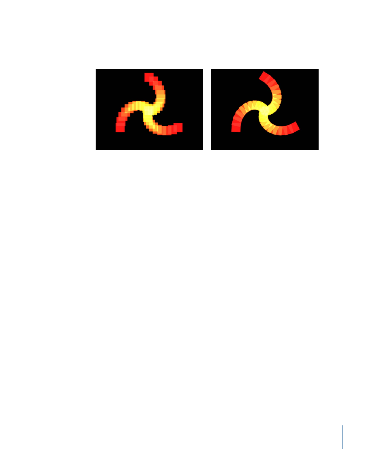
• Lines: This option is effective only when the elements of the replicator are animated
using Simulation behaviors or the Throw (Basic Motion) behavior. The movement of
each pattern element is represented by a line and is useful in analyzing the vector of
each element’s motion. The length of each line is determined by that element’s speed,
and the angle of each line equals each element’s direction. In the following image, the
replicator elements are animated using the Vortex behavior.
Note: Element movement created by the Sequence Replicator behavior or by keyframing
the replicator parameters is not displayed.
778
Chapter 15
Using the Replicator
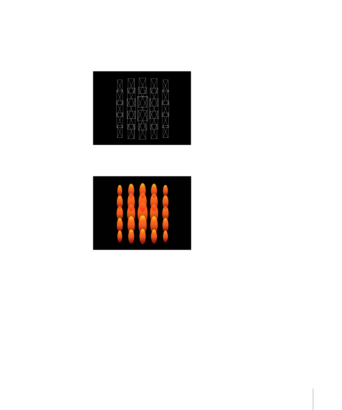
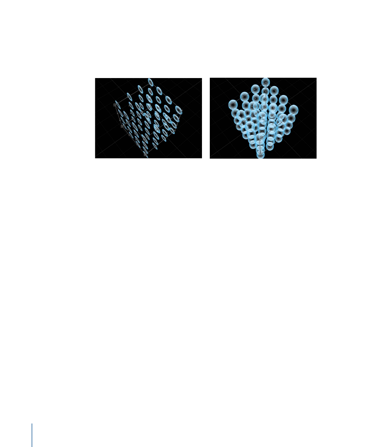
• Wireframe: Each pattern element is represented by a bounding box. Because the
bounding boxes are good indicators of each element’s orientation in the pattern, this
preview mode is useful for evaluating the movements of individual elements. For
example, it’s easy to see the angle of rotation for elements that are spinning or following
a complex motion path.
• Image: This option displays the elements as they are supposed to appear in your final
render.
Note: Whatever is selected in the Show Objects As pop-up menu appears in your final
render.
Random Seed:
Although the result of adjusting the Angle Randomness, Scale Randomness,
Pick From Color Range, Random Start Frame, or Hold Frame Randomness parameters
seems random, it’s deterministic. This means that the random variation in the pattern is
created based on the number shown in the Random Seed field. Unless this seed number
is changed, a replicator with the same parameter settings appears the same. If you don’t
like the current random scale or angle, change the seed number by typing a new number
the field or by clicking Generate.
Object Source:
This image well displays a thumbnail of the replicator. To swap out a cell,
drag a replacement cell from the Layers list to the Object Source well.
In a replicator with multiple cells, each cell appears in a separate image well listed at the
bottom of the Replicator Inspector. A checkbox allows you to enable or disable that cell.
779
Chapter 15
Using the Replicator