Modifying the Path Shape
The Text tool must be selected to view and edit the text path. Use the following procedures
to modify the shape of the path.
To adjust the text path
µ
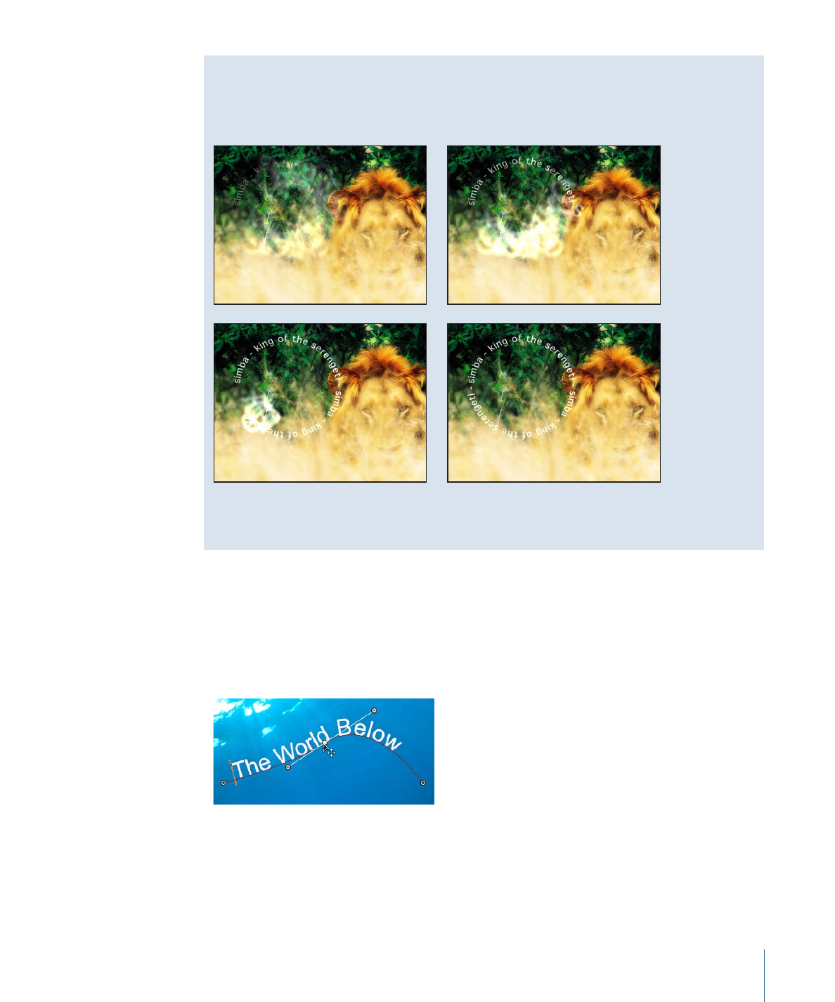
With the Text tool selected, drag a path control point to change the shape of the path.
877
Chapter 16
Creating and Editing Text
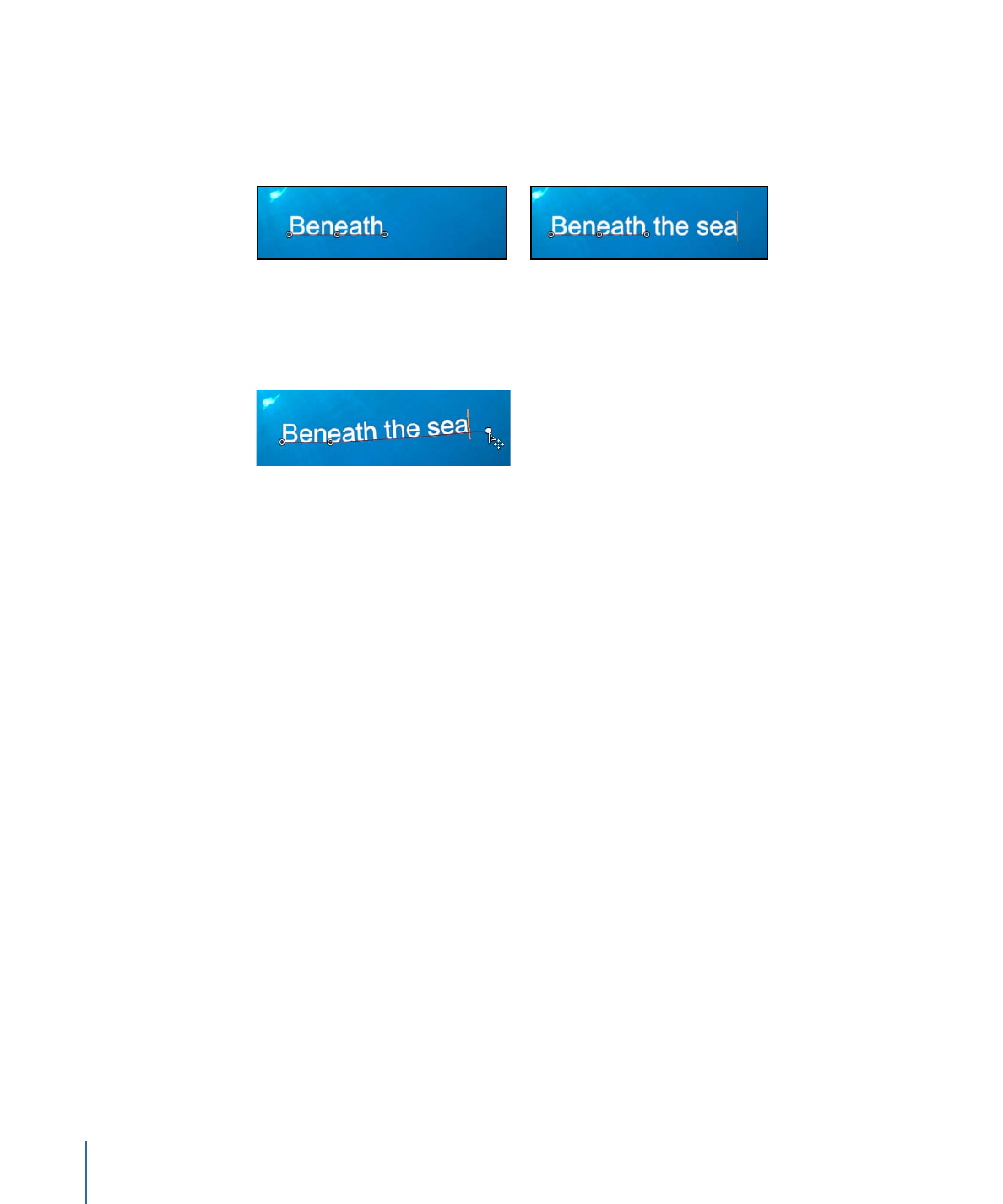
When additional text characters are added to text that is on a path, the default path may
appear too short. In the following images, the first image shows the original text placed
on a path. The second image shows additional text. In the second image with the added
text characters, the path is shorter than the text.
Additional text added
Initial text on path
To extend a text path
µ
With the Text tool selected, drag the last control point toward the end of the text.
Tip: When dragging, press Shift to constrain the path to a straight line.
After you extend a path, add control points for extra control over the shape of the path.
To add or modify text path control points
µ
Option-click or double-click the path to add a control point.
Note: Control points can only be added to Open Spline or Closed Spline paths.
µ
To remove a control point, select the point, then press Delete. You can also Control-click
the point, then choose Delete Point from the shortcut menu.
µ
To create a linear point, Control-click the point, then choose Linear from the shortcut
menu.
µ
To create a smooth (Bezier) point, Control-click the point, then choose Smooth from the
shortcut menu.
Note: When Path Type is set to B-Spline, the Very Smooth option becomes available in
the shortcut menu.
µ
To lock a point, Control-click the point, then choose Lock Point from the shortcut menu.
A locked point cannot be edited.
µ
To unlock a point, Control-click the point, then choose select Unlock Point from the
shortcut menu.
Important:
Text paths are modified in the same way as shape control points. For complete
information, see
Using Shapes, Masks, and Paint Strokes
.
878
Chapter 16
Creating and Editing Text
Note: Clicking any path control point and holding down the mouse button displays the
point number (based on the order the points are drawn on the path) and X, Y, and Z
coordinates in the status bar. Path control points are also listed by number in the Layout
pane of the Text Inspector.
To adjust the text path in 3D space
1
If there is no camera in the project, add a camera by doing one of the following:
• Click the Add Camera button in the toolbar.
• Choose Object > New Camera (or press Command-Option-C).
Note: If none of your project groups is set to 3D, a dialog appears asking you if you
want to switch your 2D groups to 3D groups. Click Switch to 3D to allow the camera
to affect the groups.
2
To change the default camera view (Active Camera) to Top, do one of the following:
• Click “Active Camera” in the upper-left corner of the Canvas to open the Camera menu,
then choose Top.
• Choose View > 3D View > Top.
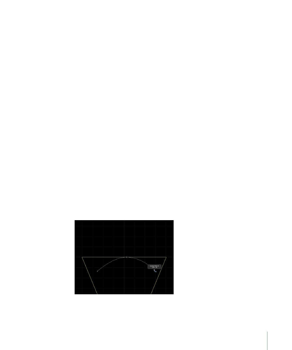
The text is no longer visible because the camera is now looking down perpendicularly
(on the Y axis) at the text on a path. The text path and its points are still visible. (The
yellow wireframe camera icon in the Canvas represents the Active Camera you added
in step 1.)
Note: The text path onscreen controls are available for all camera views. This example
uses the Top view.
3
With the Text tool selected, drag a control point to adjust the text path in X, Y, or Z space.
Note: Manipulating text on a path in 3D space only works when Path Shape is set to
Open Spline or Closed Spline.
Text on a path in 3D Top view. The right and left control
points are set to positive Z values.
879
Chapter 16
Creating and Editing Text
Tip: If the path selection disappears, reselect the text layer in the Layers list.
Note: To enter values for the control point locations for Open Spline or Closed Spline,
click the Control Points disclosure triangle in the Path Options group of the Layout pane.
The first value field is X, the second value field is Y, and the third value field is Z.
4
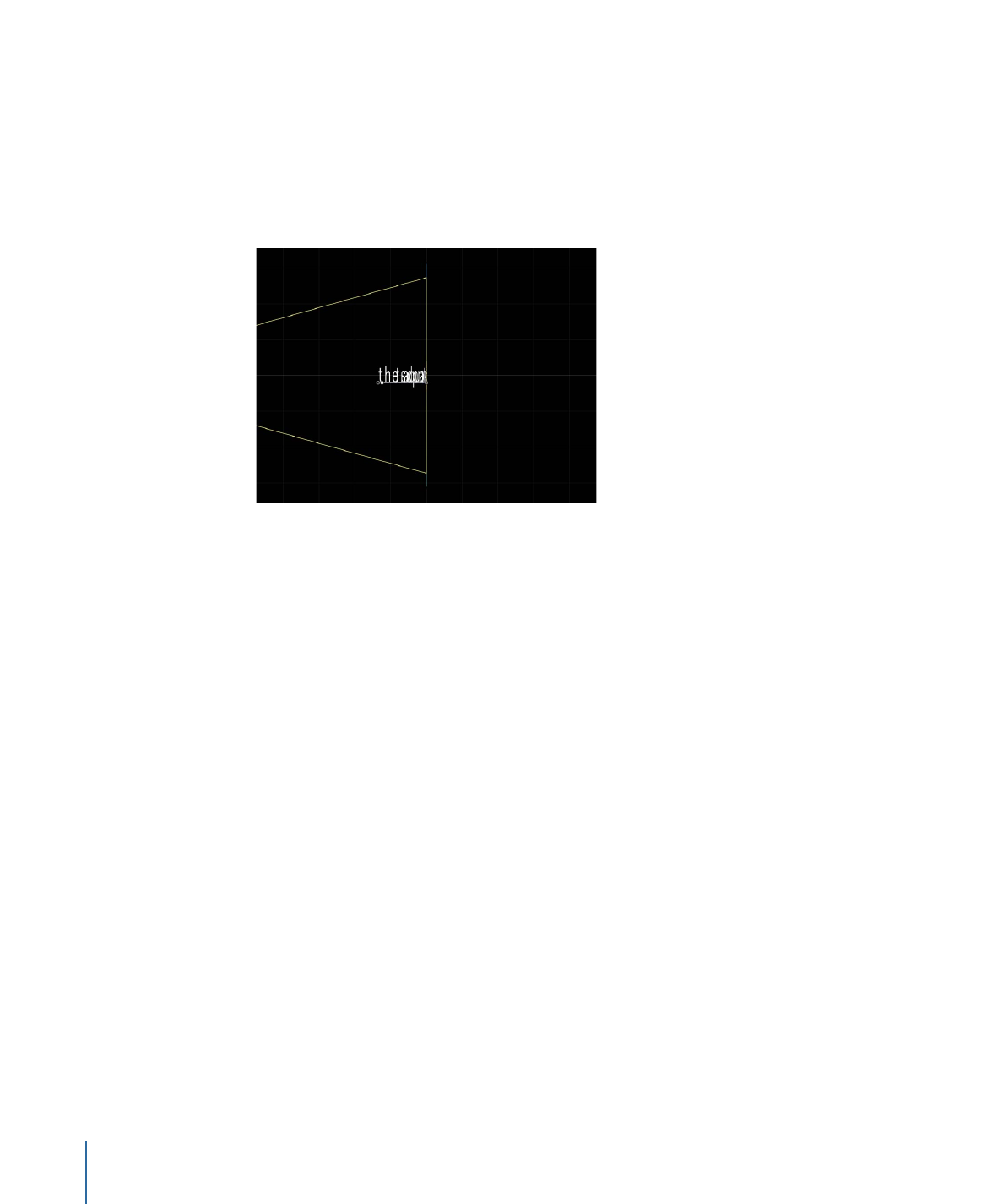
To change the camera view, choose another camera view from the Camera menu in the
upper-left corner of the Canvas.
Text on a path in Right camera view.
5
To reset the camera view, do one of the following:
• Choose Active Camera from the Camera menu.
• Choose View > 3D View > Active.
Tip: When working with text in a 3D project (especially text that moves close to the
camera), before exporting, set the Render Quality to Best (choose View > Quality >
Best). Best mode dramatically slows project performance and interactivity, so you might
want to set the Render Quality to Normal while working. You can also set the Render
Quality on export in the Export Options dialog: Choose Export, click Options, then
choose Best from the Render Quality pop-up menu. To customize an export, deselect
the “Use current project and canvas settings” checkbox.